46
f. Locate and remove 1½” NPT x 2” long black
nipple, 1½” x 1½” x ¾” NPT black tee, ¾” x ¼”
NPT black reducing bushing and Temperature &
Pressure Gauge.
g. Mount the nipple into 1½” FPT boiler supply
tapping (see Figures 1A and 1B), then, install the
tee onto the nipple, making sure ¾” branch outlet
is in horizontal plane and facing the boiler front.
h. Install ¾” x ¼” NPT black reducing bushing
into the tee branch, then, put in Temperature &
Pressure Gauge.
2. APX800 Boiler Model
a. Locate and remove (1) ¾” NPT x close black
nipple, (1) ¾” NPT x 12” black nipple, ¾” NPT
black tee, ¾” FPT x 1” FPT Pressure Relief
Valve, ¾” NPT Drain Valve.
b. Install close nipple into tee branch, then, screw
the assembly into boiler left side front ¾”
tapping making sure tee run outlets are in vertical
plane and parallel to boiler side.
c. Install the ¾” NPT x 12” black nipple into tee
run top outlet.
d. Mount ¾” FPT x 1” FPT Pressure Relief Valve
onto 12” nipple.
e. Install Drain Valve into the tee bottom outlet.
f. Locate and remove 2” NPT steel coupling, 2”
NPT x 2-1/2” long black nipple, 2” x 2” x ¾”
NPT black tee, ¾” x ¼” NPT black reducing
bushing and Temperature & Pressure Gauge.
g. Mount 2” NPT coupling onto 2” MPT boiler
supply stub (see Figure 1C), then, install 2”
NPT x 2-1/2” long black nipple into the coupling
VI. Water Piping and Trim A. Factory Supplied Piping and Trim (continued)
Boiler
Model
Boiler
Supply
Connection,
Inch, FPT
Boiler
Return
Connection,
Inch, FPT
Minimum
Required
Flow (GPM)
@ 35°F DT
Boiler
Head Loss,
Ft.
@ 35°F DT
Required
Flow,
(GPM)
@ 30°F DT
Boiler
Head Loss,
Ft.
@ 30°F DT
Required
Flow,
(GPM)
@ 25°F DT
Boiler Head
Loss, Ft. @
25°F DT
Maximum
Required
Flow (GPM)
@ 20°F DT
Boiler
Head
Loss, Ft.
@ 20°F DT
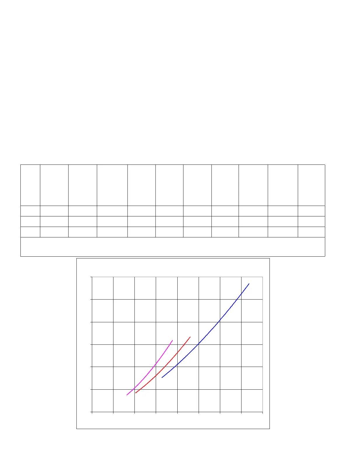
APX399 1½ 1½ 21.5 6.1 25.1 7.9 30.2 10.8 37.7 15.9
APX500 1½ 1½ 27.1 6.9 31.7 8.9 38.0 12.1 47.5 17.6
APX800 2 2 43.4 12.1 50.7 15.5 60.8 20.9 76.0 30.0
Notes: Required Flow (GPM) = ** Output (MBH) * 1000/500 * DT
** Output (MBH) - Select Value for specic Boiler Model from Table 2A or 2B
Using boiler antifreeze will result in higher uid density and may require larger circulators.
Table 14: Flow Range Requirement Through Boiler
399
500
800
0
5
10
15
20
25
30
0 10 20 30 40 50 60 70 80
Flow Rate (GPM)
Pressure Drop (Feet of Head)
 Loading...