23
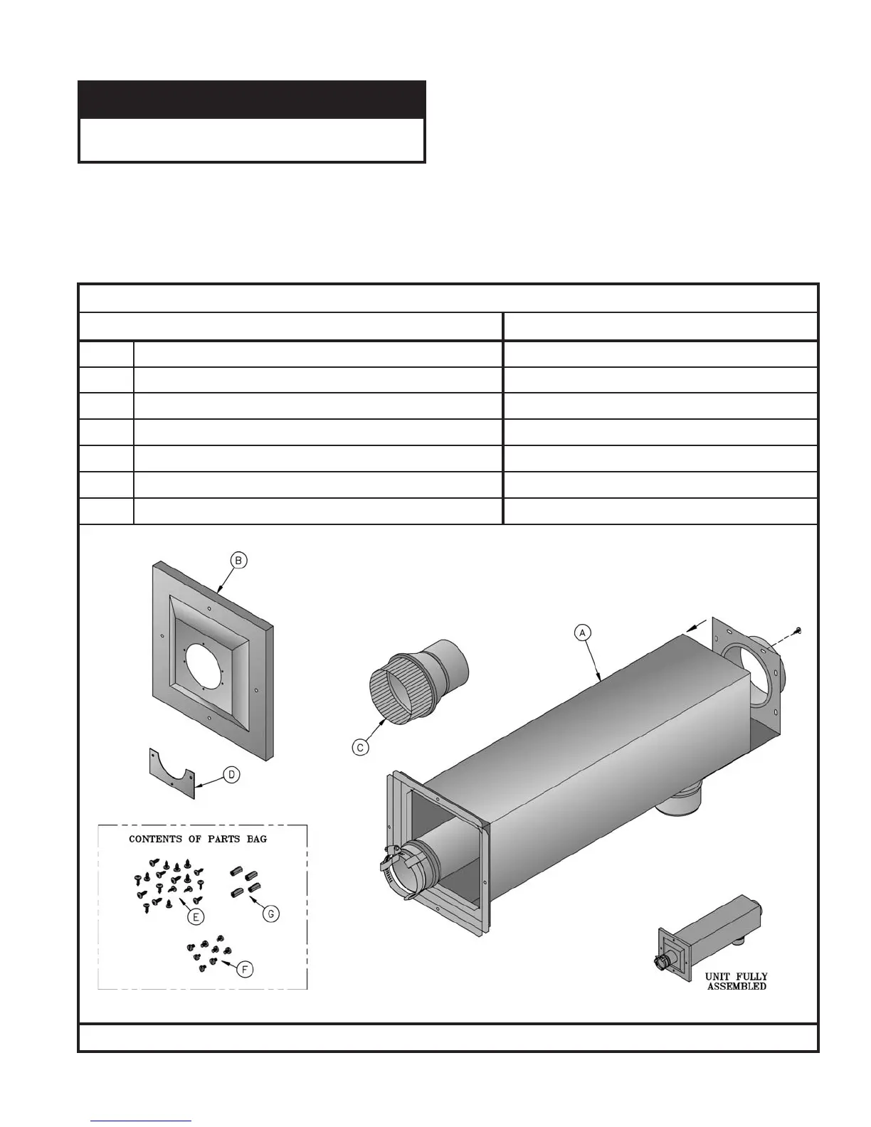
F. Combination Horizontal Venting System –SCG-3 Through SCG-6 ONLY – See Figures 10 and 11.
ECITON
tonstnenopmocseriuqermetsystnevsihT
.reliobehthtiwdeilppus
1. Do not exceed maximum vent/air intake lengths.
Refer to Table 4.
2.
Install Combination Vent/Air Terminal. See Figure 11.
a. After determining the location with reference to Section B - General Venting Guidelines, cut a 6-1/8 inch square
opening in the wall for the air box sub-assembly which is 6 inch square.
b. Remove and save shipping screw from end panel with collar and vent pipe assembly. This will be reinstalled in a later
step.
21060116rebmuNtraPnotraCtneV)wolebsmetisedulcni(
noitpircseDrebmuNtraPtnenopmoC
A)gnol'2xerauqs"6(ylbmessA-buSxoBriA 11060116
B)erauqs"01(revoCllaWroiretxE 61060117
CrecudeRepiPtneV"3x"4 93
26118
D)2(revoCroiretxElaeS-etalP 71060117
E)91(wercSlateMteehSleetSsselniatS"½x8# 74006808
F)8(wercSenihcaMleetSsselniatS"¼x23-01# 24806808
G)4(recapSmunimulA"½x23-01# 71616808
STNENOPMOCMETSYSTNEVLATNOZIROHNOITANI
BMOC
 Loading...