15 of 24
5 Installation
5.1 Mechanics
Mounting surface
A high quality measurement depends on a defined deformation of the measuring element under load. To
be certain of excluding any unwanted deformations, the model 8524 tension and compression load cell
must lie flat on the mounting surface.
The mounting surface must meet the following requirements:
• adequately stable
• hardened, minimum hardness 60 HRC
• polished, preferably lapped, surface quality: N3 (Rz 1), evenness 2 µm
• not coated in any material
• must contain no holes or milled slots, or any centering holes
• be flat
IMPORTANT: Prevent torsional moments, lateral forces and bending forces.
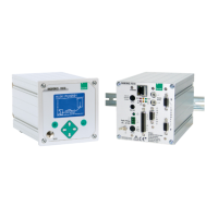
Application of force
1. Apply the force being measured to the model 8524 tension and compression load cell via
the central thread.
2. Apply the force centrically exactly along the axis of symmetry.
IMPORTANT: Eliminate any lateral forces and torques.
NOTICE
• The force application components must be ground flat (never convex) and lapped.
• The material must be hardened, not just surface-hardened, and have 60 HRC
hardness.
• In the force application component there must not be any holes in the effective
surfaces such as centering holes for lathes or grinding machines.
• The specifications are valid exclusively with the provided load buttons.
Figure 4: Applying force to the 8524
Note: burster offers pull plates (model 8590) for all measuring ranges of this model 8524 tension and
compression load cell. These allow force to be applied on both sides via the central internal
thread.