16 of 24
Overload
You can recognize an overload from an increased output signal at no load. Bending plates are relatively
insensitive to overloading.
Note: Check the model 8524 tension and compression load cell if the signal increases by more than
approx. 5%.
NOTICE
• Do not apply sudden loads to the model 8524 tension and compression load cell.
• Dynamic loads above 70% of the rated force reduce the life of sensors.
• If used as a weighing device via axles or entire vehicles, use design measures to
absorb the dynamic loading (due to driving onto ramps, braking vehicles, etc.)
• Make sure that the load does not generate any lateral forces.
• Use design measures to prevent lateral forces caused by thermal expansion if the
model 8524 tension and compression load cell is used as a weighing device on
containers.
5.2 Fixing method
The entire contact surface of the model 8524 tension and compression load cell must lie on a hardened
(60 HRC), flat, ground or lapped mounting surface.
Bolts
Note: Refer to the latest data sheet for the maximum bolt torques for mounting the model 8524
tension and compression load cell. In addition, we recommend monitoring the sensor’s output
signals during installation via a display to detect and prevent possible improper loads during
installation at an early stage.
Only use bolts that have the following characteristics:
• Bolt strength 12.9 or higher
• Hex socket head bolts to DIN 912
• Countersinks to DIN 74 Km
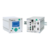
Measuring ranges up to 0 to 2 kN:
Figure 5: 3 through-holes with point-contact mounts for three-point mounting
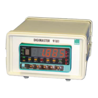
Measuring ranges from 0 to 5 kN:
Figure 6: 6 or 8 through-holes