Electrical Connection | 6
Instruction Manual R5 KB KC 0010-0016 E_EN_en 13 | 32
● Provide a lockable disconnect switch on the power line so that the machine is completely secured
during maintenance tasks.
● Provide an overload protection according to EN 60204-1 for the motor.
● Busch recommends installing a D-curve circuit breaker.
● Connect the protective earth conductor.
● Electrically connect the motor.
NOTICE
Incorrect connection.
Risk of damage to the motor!
● The wiring diagrams given below are typical. Check the inside of the terminal box for motor con-
nection instructions/diagrams.
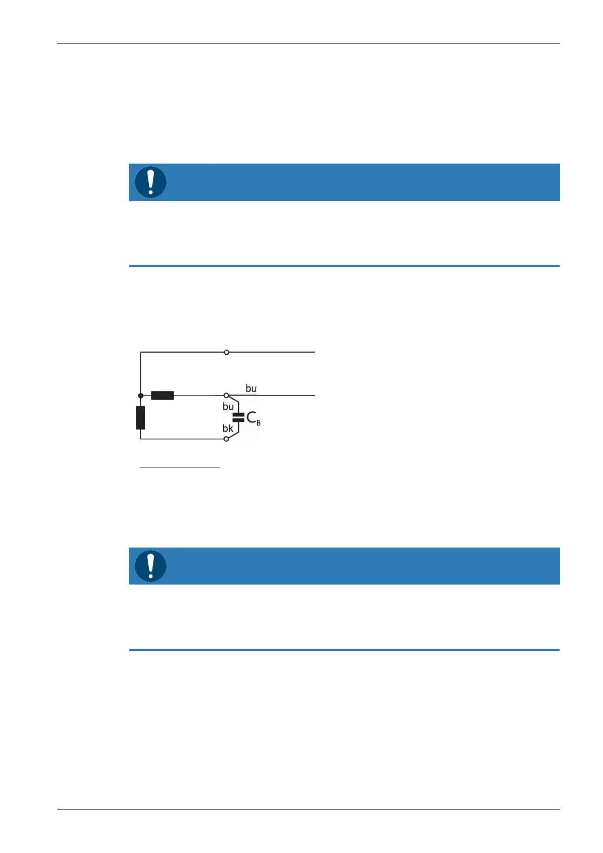
6.2 Wiring Diagram Single-Phase Motor
Motor with connection cable:
Ha = Main phase
Hi = Auxiliary phase
C = Permanent capacitor
bk = Black
bn = Brown
bu = Blue
ye/gn =Yellow/green
6.3 Wiring Diagram Three-Phase Motor
NOTICE
Incorrect direction of rotation.
Risk of damage to the machine!
● Operation in the wrong direction of rotation can destroy the machine in a short time! Prior to
start-up, ensure that the machine is operated in the right direction.
● Determine the intended direction of rotation with the arrow (stuck on or cast).
● Jog the motor briefly.
If the rotation of the motor must be changed:
● Switch any two of the motor phase wires.