RTG SERIES TILLER 05/16 Assembly Section 3-3
© 2015 Alamo Group.Inc.
ASSEMBLY
ASSEMBLY
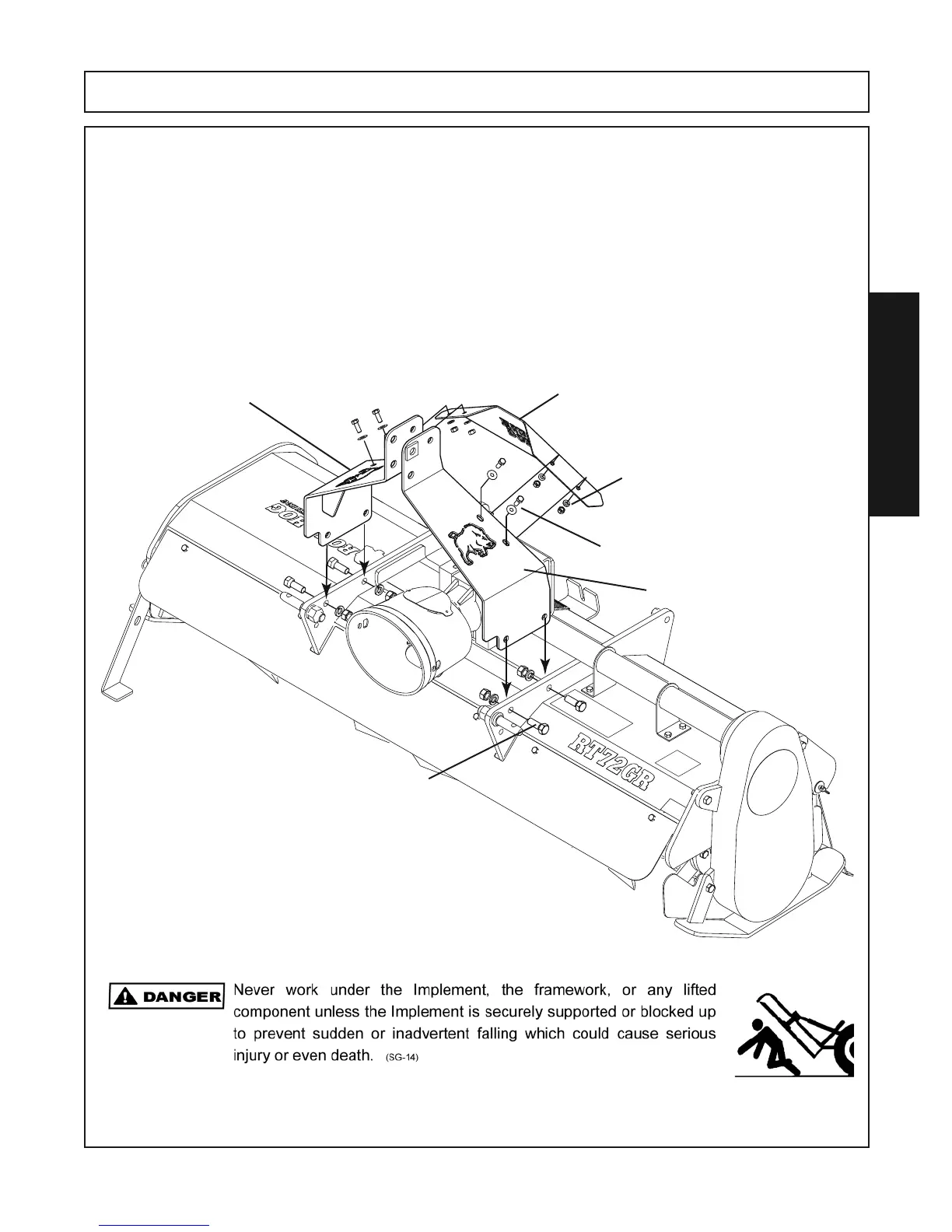
8. Carefully remove the “A” Frames, Mast Bars, “A”Frame Cover and bag of fasteners at-
tached to the top of the machine for shipping.
9. Attach the R.H. and L.H. “A” Frames to the Inside of the frame braces. From the bag of
fasteners use (4) 5/8” x 1-3/4” Gr. 5 capscrews, (4) 5/8” lockwashers & (4) 5/8” hex nuts.
Leave fasteners finger tight at this point.
10. Assemble the “A”Frame Cover to the inside of the “A” Frames using (4) 3/8” x 1” cap-
screws, (4) 3/8” flatwashers (on the outside of the “A” Frame against the slotted holes), (4)
3/8” lockwashers & (4) 3/8” hex nuts from the bag of fasteners.
“A” Frame Cover
L.H. “A”Frame
R.H. “A”Frame
5/8” x 1-3/4” Capscrew (4) Places
5/8” Lockwashers (4) Places
5/8” Hex Nuts (4) Places
3/8” x1” Capscrew (4) Places
3/8” Flatwashers (4) Places
3/8” Lockwasher () Places
3/8” Hex Nut (4) Places