© Alamo Group.Inc.
RTG SERIES TILLER 05/16 Assembly Section 3-8
ASSEMBLY
ASSEMBLY
CONVERTING FROM STANDARD ROTATION TO REVERSE ROTATION
To convert the RTG Tiller, standard rotation to a reverse rotation will require the purchase of a Safety Shield to
prevent debris from entering the Operator area during operation. The required parts may be ordered from a
Bush Hog Dealer.
Required parts are as follows:
RTG60 Shield number 50075506
RTG72 Shield number 50075093
RTG84 Shield number 50075507
Attchment will require six (6) 3/8” x 1” Grade 5 bolts and six (6) 3/8” Locknuts.
Serious Injury or Death could occur if not taking the time to secure the Tiller to pre-
vent the machine from falling or tipping while performing this procedure.
SAFETY FIRST
Park the Tiller on a hard level surface. Lower the parking stand and securely block the machine so it cannot tip
or roll over during this procedure.
Disconnect the tiller from the tractor and move the tractor away from the tiller.
Note: In the following illustrations the lift frame and struts are not pictured for clarity. It is not necessary
to remove these items.
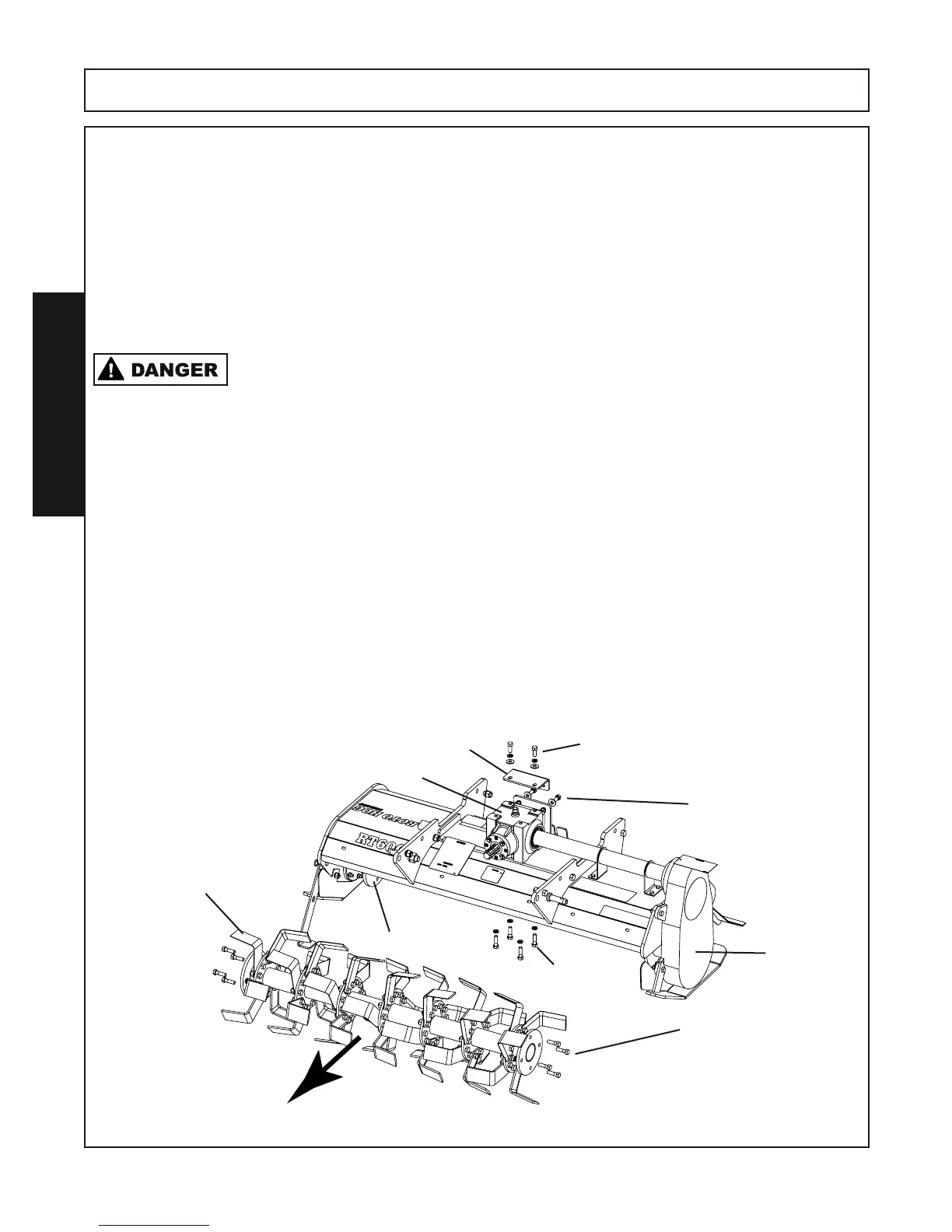
Step 1. Remove the driveline from the gearbox assembly. Remove the input shaft shield from the front of the
gearbox. Retain all fasteners for reinstallation.
Step 2. Remove the eight 1/2” x 1-3/4” bolts, hex nuts and lockwashers attaching the Tine Bar to the Side
Gearbox and the Right Side Hub. Carfully roll the Tine Bar from under the tiller mainframe out of the
way.
Step 3. Remove the 1/2” x 1-1/4” bolts, lockwashers and flatwashers attaching the Gearbox to the Gearbox
Plate. Loosen the 1/2” x 1-1/2” bolts, lockwashers and flatwashers attaching the Gearbox Plate to
the rear bracket.
Step 4. Remove the four 1/2” x 1-3/4” bolts and lockwashers located on the underside of the frame attaching
the Gearbox.
Tine Bar Assembly
Gearbox Plate
Gearbox
1/2” x 1-3/4” Bolts
Lockwashers
Hex Nuts
(Both Ends)
1/2” x 1-3/4” Bolts
Lockwashers
1/2” x 1-1/4” bolts
lockwashers
flatwashers
1/2” x 1-1/2” bolts
lockwashers
flatwashers
Hex Nuts
Side
Gearbox
Right Side Hub