RTG SERIES TILLER 05/16 Assembly Section 3-4
© 2015 Alamo Group.Inc.
ASSEMBLY
ASSEMBLY
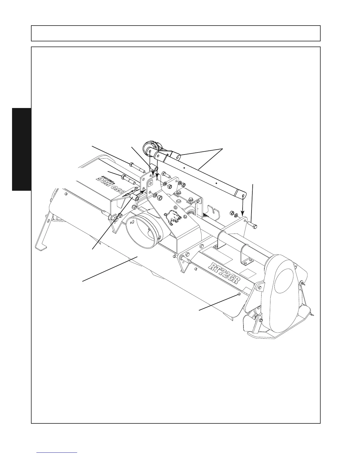
11. Attach the 2 Mast Bars to the inside of the frame braces using (2) 5/8” x 2” Gr.8 capscrews, (2) 5/8” Lock-
washers, (2) 5/8” Hex Nuts.
12. Place the Mast Bars to the outside of the top rear hole of the”A” frame. Place a bushing (2” long x 1.25”
diameter) between the “A” frame, align holes. Fasten with a 5/8” x 4-1/2” Gr.5 capscrew, 5/8” lockwasher &
5/8” hex nut.
13.To the lower hole at the top front of the “A” Frame place a bushing (2” long x 1.25” diameter) between the
“A” frame, align holes and install a 3/4” x 3-3/4” Gr.5 capscrew,3/4” lockwasher & 3/4” hex nut.
14.Tighten ALL fasteners.
Mast Bars
Bushing
Bushing
5/8” x 2” Gr.8 Capscrew (2 Places)
5/8” Lockwasher (2 Places)
5/8” Hex Nut (2 Places)
3/4” x 3-3/4” Gr.5 Capscrew
3/4” Lockwasher
3/4” HexNut
5/8” x 4-1/2” Gr.5 Capscrew
5/8” Lockwasher
5/8” HexNut
RTG60GR, RT72GR, RT84GR REVERSE ROTATION MODELS ONLY
Attach the metal shield to the front of the Tiller using (6) 3/8” x 1” Capscrews and (6) 3/8” Locknuts.
Metal Shield
Reverse Rotation Models Only
3/8” x 1” Capscrew (6) Places
3/8” Locknut (6) Places