8
GB
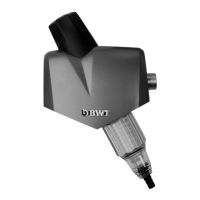
2. Scope of Supply
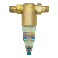
Complete BWT Diago RF (Fig. 1) consisting of:
• Top section in brass
• Connection ttings (1) incl. seal
• Transparent cylinder with lter element (2)
• Waste water connection (hose nozzle) (4)
• Filter element
• Turning knob for the backwashing element (5)
• Cover incl. Automatic Hygiene Advice (AHA) (6)
3. Application
This lter is intended for the ltration of drinking
and service water. It protects the water pipes and
the connected water system parts from malfunctions
and corrosion damage due to impurities such as
rust particles, chippings, sand, hemp, etc.
The lter cannot be used in applications with che-
mically treated circulating water, process water
and cooling water for continuous cooling systems.
In applications with water containing coarse impu-
rities, a coarse dirt separator must be used. The
lter is not suitable for oils, greases, solvents, soaps
and other lubricating media or for the separation of
water-soluble substances.
Attention: In accordance with AVB Wasser V, §
12.2, the installation of the equipment may only
be carried out by the public water supply company
or by an installation company listed in the installer
directory of a water supply company.
4. Function
The untreated water ows through the untreated wa-
ter inlet into the lter and from there from the inside
to the outside through the lter element into the clean
water outlet (Fig. 1).
Any impurities > 90 μm are trapped on the inside
of the lter cloth. The lter element needs to be clea-
ned by backwashing at regular intervals. For the
backwashing process, the waste water connection
is opened by turning the turning knob and the back-
washing element is also turned. The particles on the
lter cloth are removed by suction and then washed
out.
5. Installation conditions
Observe the local installation regulations, general
guidelines, general hygiene regulations and the
technical specications. A connection to the sewage
system (discharge) of min. DN 40 should be availa-
ble.
Install lter concerning the nominal with in equal
dimensioned water pipes for cold water (Fig. 3) in
front of the objects to be protected. Always provide
stop valves. Install lter in the direction of ow in
the horizontal cold water pipe (observe direction of
ow arrow).
Attention: The installation site must be protected
against frost and must ensure the protection of the
lter against e.g. solvent vapours, fuel oil, lees, che-
micals of any kind, UV radiation and heat sources
above 40 °C.
Attention: Keep the plastic parts free from grease,
solvents and acidic as well as basic detergents. The
plastic parts must be replaced even if there is no
visible damage after severe concussions and shocks
e.g. due to the use of unsuitable tools or if dropped
on stone oors etc (danger of bursting). Avoid extre-
me pressure impact.
6. Installation
Remove the cover. Install the connection ttings and
place the lter in between in the right ow direction.
Then ret the cover and the turning knob. Connect
the waste water connection with a hose and put the
other and of the hose in a suitable drain (or a bin
with a minimum of 10 l volume).
Please note: According to DIN 1988, the ushing
water hose must be installed at a minimum distance
of 20 mm to the highest possible waste water level
(free discharge).
2989_EBA Diago AHA 332363-3.indd 8 13.07.11 09:57