GB
ind.1 du 16/10/2012 6 EUROMAT 2 P0011049
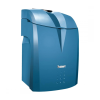
EUROMAT 2 is a water softener for domestic use, which
makes it possible to distribute softened water from a
town water network. A system of residual total hardness
adjustment, which is incorporated into the equipment,
makes it possible to mix the softened water. EUROMAT 2
is a compact softener unit including:
1 Head of the softener and an electronic
control box
2 Transformer for a 230V, 50/60 Hz electrical
supply and its connectors
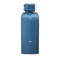
3 Softening column with the ion exchange resin
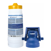
4 Compact unit with a regenerating salt
reservoir
5 Brine reserve
6 Overflow for 12/16 flexible hose (hose not
supplied)
7 Salt gate for topping up
8 Regeneration water discharge connection
9 Brine connection for regeneration (6/8 hose
supplied)
10 Input for water to be treated with flexible hose
F 1"
11 Output of treated water with flexible hose F 1"
12 Adjustment of residual hardness
13 Brine valve for brine intake and reservoir
feeling
FIELD OF UTILISATION
The utilisation of the EUROMAT 2 softener must in all
circumstances observe the regulations and legislation in
force in the locality, the establishment or the country in
which the equipment has been installed.
CONDITIONS OF INSTALLATION
It is essential to observe local regulations on installation,
general directives, general conditions of hygiene, safety
and technical data of the system.
The electrical supply for the EUROMAT 2 of 230V and
50/60 Hz and the operating pressure required for the
good functioning of the equipment must be
guaranteed in permanence. The system is not equipped
with a water-hammer protection device and/or a lack
of water, and therefore, if necessary, an adequate
device should be introduced.
A protective filter (not supplied) must be installed
upstream of the EUROMAT 2.
A connection to a drain for evacuating rinse water (of a
minimum diameter of 50 mm) must be placed close to
the installation.
If necessary and if the operating pressure is higher than
2.1 bars, the rinse water hose can be placed up to
1.5 metres above the softener. In that case, it is
necessary to lengthen the recommended duration of
regeneration.
The overflow pipe of the brine reservoir (not supplied)
must be inclined and allow outflow by gravity to the
drain or possibly to a lifting system, which must resist
brine. The output of the system will be determined so
that the regeneration water from the EUROMAT 2 is
evacuated correctly.
If the circuit pressure is greater than 6 bars, a pressure
reducer upstream of the installation must be installed in
order to obtain an operating pressure of approximately
4 bars.
The place of installation must be protected from frost,
and the installation must be protected from the ingress
of any chemical substances, dyes, detergents, greases
and vapours. The ambient temperature must not
exceed 40°C and that of the water to be treated a
maximum of 30°C. The softener must be accessible for
maintenance and rest on a flat level surface, provided
for supporting the weight of the softener when
operating (table 1).
ASSEMBLY ( REFER TO DRAWINGS )
The hydraulic connection of the EUROMAT 2 must be
effected using the flexible hoses supplied (delivered in
the salt tank, fig.A-1). Observe the direction of the fluid
shown by the arrows (fig.B), connect the water to be
treated to the 1" female connection on the left and the
water output also to a 1" female connection on the
right.
Then, connect the canalisation (fig.B-2) for the intake of
brine. After having withdrawn the salt gate (fig.A-2), grip
the grey 6/8 hose in the salt tank and pass it through the
interior hole to the outside of the tank. Connect the end
of the grey 6/8 hose to the valve of the softener (fig.B-2)
and hold it in place with the finned connector provided
for that purpose. Connect the flexible hose of internal
diameter 12 mm (delivered in the salt tank) to the
ribbed regeneration water connector (fig.B-1) and lead
it to the drain, observing a charge break of at least 2
centimetres. Finally, connect the overflow to the ribbed
connector of the salt tank (fig.A-3) with a diameter of 12
mm with a 12/16 flexible hose (not supplied) and lead it
to the drain (flow must be by gravity).
To supply electric current to the EUROMAT 2, connect
the transformer to the installation standard electric
current socket provided for that purpose, which must be
located close to the installation (maximum 1.5 metres).
PROGRAMMING.
On being placed under voltage, the LCD display (fig.C-
1) lights. For correct functioning it is necessary to
program the EUROMAT 2. Modify the values displayed
by using key 3 (fig.C-T3) to move the selection to the
right and key 4 (fig.C-T4) to modify the value of the
selected digit (flashing). Proceed to the programming,
carefully observing the stages described below. Without
actuation of the keys for 30 seconds, the instrument
returns to its initial state. Press key 2 (fig.C-T2) for 5
seconds in order to resume programming and then, by
means of pulsing, reach the interrupted stage.
If the display (fig.C-1) shows 5 zeros the first of which, on
the left, flashes, it is necessary to enter the code "12120"
for volumetric functioning "SE" (equipment fitted with an
inside watermeter). Next, validate your entry with the
hidden key (fig.C-T5).
To modify the code, simultaneously press the keys 2
(fig.C-T2) and 5 (fig. C-T5), for about 5 seconds release
them and then restart the above procedure.
 Loading...