20
GRID
L N PE
LOAD
L N PE
RCD RCD
load load
N Bar
PE Bar
L
N
GRID
MET
ER
MIN ES
Main Swicth
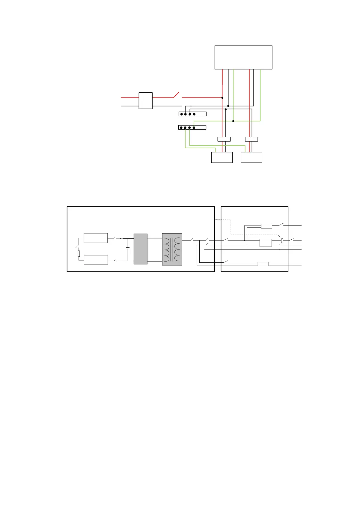
figure4. Electrical distribution diagram
H
L
Off Grid
Grid
N
PE
Battery1
Battery2
KM4
KM5
KM1
KM2
+
-
-
+
K0
CT
KM3
N
L
MINES(Battery Energy Systerm)
T
RCD
RCD
K1
METER
K2
K3
K4
Load
CT
fuse
Distribution Box
figure5. Electrical block diagram
Note:
1、K0、K01 is battery switch,K1 is grid-connected switch,K2 is major load switch,K3 is load
switch,K4 is total grid switch.
2、Add a RCD in OFF-GRID port and GRID port to avoid that leakage of electrical equipment
endangers human safety.
3.4 Overview of functions
The MINI ES operates in several working conditions depending on the system status: