Relay output wiring
Four volt-free relay output connections are provided - a failsafe fault output*, which switches for any
fault condition and three programmable auxiliary relay outputs. All four relays are capable of switching
1A @ 30Vd.c. and MUST NOT be used for directly switching mains voltages.
* In the event of total de-energisation of the fire panel the fault relay will change state.
The three auxiliary outputs (Relays 1, 2 and 3) can be programmed using the panel’s PC programming
tools to operate as required but their default operations are:
Relay 1 : Switches when any zone goes into fire, switches back when the panel is silenced.
Relay 2 : Switches when any zone goes into fire, switches back when the panel is reset.
Relay 3 : Has no default operation.
It is recommended that customers wire to the normally closed
(N/C) terminals on the fault relay, as this is standard industry
practice.
Fig.8 (right) shows how the outputs work.
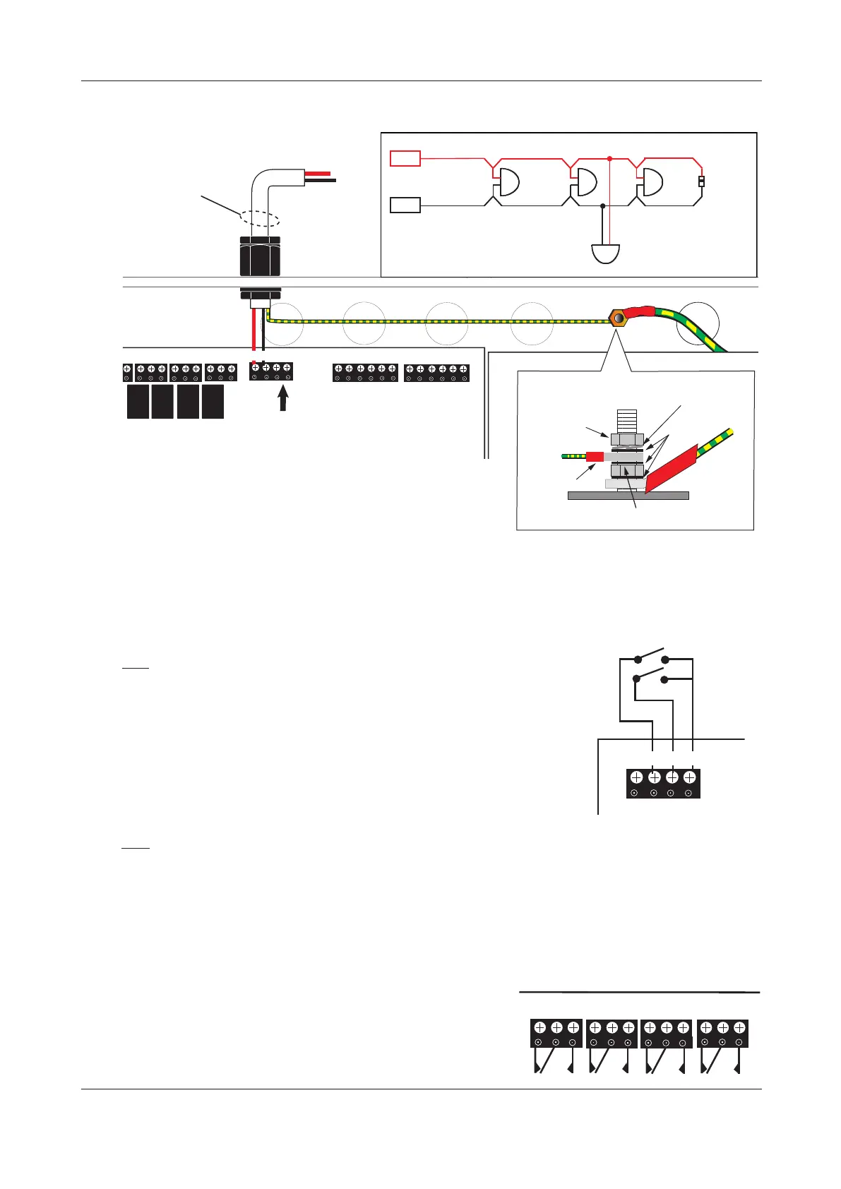
Fig.6 : Typical conventional sounder circuit connection
ENGINEERING MANUAL • Approved Document No. DFU5010020 Rev 4 • Page 11 of 48
CAST XFP 32 ZONE ANALOGUE ADDRESSABLE FIRE ALARM PANEL
Fault
NC C NO
RLY3
NC C NO
RLY2
NC C NO
RLY1
NC C NO
+24v I/P1 I/P2 0v
I/O
Sounder
Circuits
Eth B+ B-Eth A+ A-
LOOP 2
LOOP 1
Additional Conventional
Sounder Circuit S2
(if required)
Main Control
PCB
Eth B+ B-Eth A+ A-
+ S1 -+ S2 -
Conventional Sounder
Circuit S1
screens
POLARISED
SOUNDER
+ + +
-
+
+
✗
POLARISED
SOUNDER
POLARISED
SOUNDER
EOL
RESISTOR
(6k8 ohm)
DO NOT SPUR
(Wiring not monitored)
SOUNDER
CCT 1
Auxiliary input wiring
Two programmable auxiliary input connections (non-monitored) are
provided. These can be programmed using the panel’s PC programming
tools to operate as required. The wiring for each input should be connected
to the Main Control PCB terminals marked: I/O, as shown in Fig.7 right.
If applicable, i.e. in electrically noisy environments, input wiring screens
should be terminated at the panel’s base earth distribution post, as
detailed in Fig.6 above.
Fig.7 : Typical auxiliary input wiring
Fig.8 : Relay output detail
Fault
NC C NO
RLY3
NC C NO
RLY2
NC C NO
RLY1
NC C NO
Input 1
Input 2
+24v I/P1 I/P2 0v
I/O
Note about earthing of screens
All screens should be adequately insulated and connected between
the nut and washers on the base earth distribution post using
crimp connectors. The base earth distribution post is provided
for terminating earth screens or drains and is NOT the main earthing point. The installer must review the
external earth bonding (if required) with respect to the national wiring rules. If the installation requires
protective earth bonding, then this must be applied externally and in conjunction with the type of earthing
system employed on site.
nut
3 x plain
washer
crimped
connection
Do not untighten lower nut
spring
washer
screens
Base Earth Distribution Post
PSU Earth
Distribution
Strap
 Loading...
