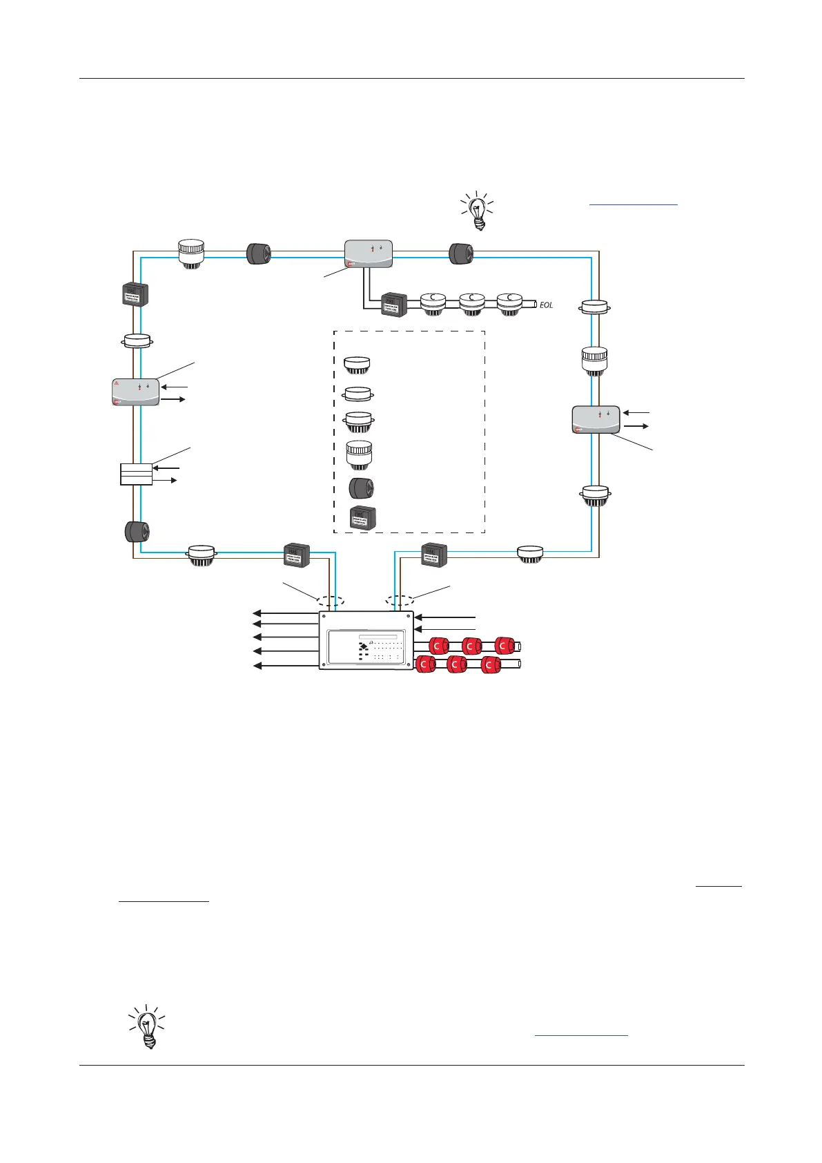
Analogue addressable loop wiring
Fig.4 below shows a typical analogue addressable loop complete with detectors, manual call points,
loop-powered sounders/VADs and I/O units. Connect the loop to the relevant 5mm connector block on
the Main Control PCB and terminate screens at the panel’s earth (Eth) terminals, as detailed on page 10.
Fig.4 : Typical analogue addressable loop
Polling
Active
Input Fault
CAST Zone
Monitor Unit
Conventional manual call points & detectors
Polling
Active
Input Fault
CAST I/O Unit
Fire Output
Fault Input
Input Fault
Polling
Active
CAST Mains Switching
I/O Unit
Mains Switching Output
Monitored Input
CAST XFP 1/2 LOOP
32 ZONE MAIN PANEL
Auxiliary Input 1 (programmable)
Auxiliary Input 2 (programmable)
Conventional Sounder Circuit 1 (programmable)
Conventional Sounder Circuit 2 (programmable)
Relay Output 1 (programmable)
Relay Output 2 (programmable)
Relay Output 3 (programmable)
Fault Relay Output
100mA, +24Vdc Output
CAST Mini I/O Unit
Relay Output
Monitored Switch Input
Compact Sounder or VAD
or Sounder VAD
Base Sounder or VAD
or Sounder VAD
Base c/w Detector
Hi-Output Sounder
or Sounder VAD
Manual Call Point
CAST Loop Devices
Detector c/w mounting
base on Sounder/VAD
Loop 1
(Loop 2 not
shown)
LOOP 1 A (OUT)
LOOP 1 B (RETURN)
Design issues - reducing faults and their consequences
To ensure a reliable system, it should be designed and maintained to local design and installation
regulations. The CAST XFP panel has a short circuit protected loop driver fitted and also short circuit
isolators fitted in every CAST loop device. A single short circuit or open circuit fault will have no detrimental
affect on the operation of the system but a loop integrity fault will be shown at the panel.
Note that a critical design issue with any analogue fire system is the combined effect of loop resistance,
loop capacitance and the current demand of devices connected to the loop. Factors that influence this
include loop length, cable diameter, cable type and the number and type of devices. There are no hard
and fast rules regarding these factors as every situation is unique. However, if the following general
rules of thumb are followed, the loop WILL almost certainly work.
• Absolute maximum loop length = 1km, with either 1mm
2
or 1.5mm
2
cables.
• If loop sounders are required, use 1.5mm
2
cable and DO NOT fit more than the maximum circuit rating
detailed in the technical specification (see page 48).
The above SHOULD NOT be considered the maximum panel operating conditions as many other
permutations are possible. Always refer to the supplied device instructions before installation.
Hint! An XFP Loop & Battery Calculator Tool is available for download on C-TEC’s website in
the Support Hub to assist with system designs (available @ www.c-tec.com).
ENGINEERING MANUAL • Approved Document No. DFU5010020 Rev 4 • Page 9 of 48
CAST XFP 32 ZONE ANALOGUE ADDRESSABLE FIRE ALARM PANEL
Hint! Refer to www.c-tec.com for C-TEC’s
CAST range of compatible devices.
 Loading...
