14 14
4 Replacing Assembly Units
4.5 Replacing the PCB CPU
Danger!
Risk of death via electric shock!
Before opening the housing cover, disconnect the device from the mains supply and wait at least one
minute until the power supply unit has discharged.
1
2
1
3
4
5
7
8
9
1
1
6
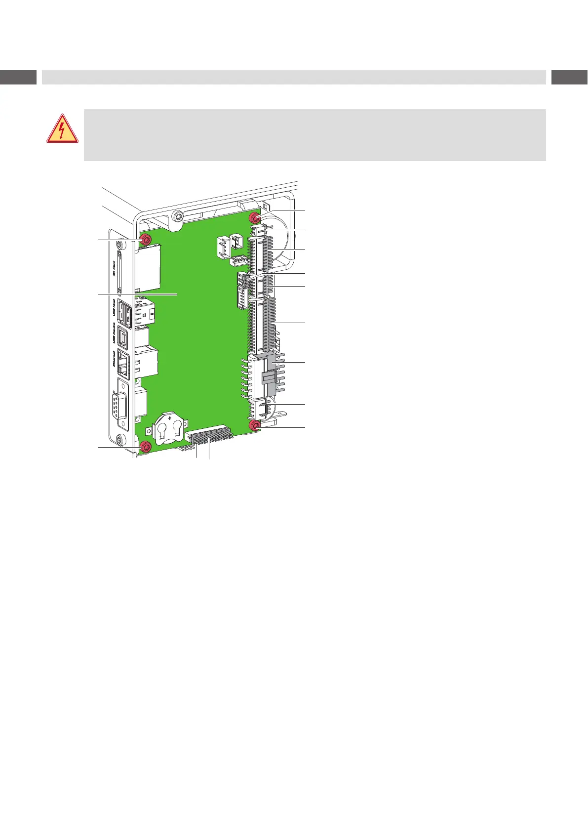
1 4 screws
2 PCB CPU
Connectors
3 CON17 - Switch locking system
4 CON12 - Control panel
5 CON15 - Winding sensor
6 CON11 - Sensors
7 CON10 - Printhead
8 CON9 - Power supply
9 CON8 - Stepper motor
10 CON7 - I/O interface
Figure 9 Replacing the PCB CPU
1. If possible, save the printer conguration to an external medium Conguration Manual.
2. Unplug the printer from the electrical outlet.
3. Detach all interface cables from the back of the printer.
4. Remove all memory media from the slots.
5. Dismount the rear cover.
6. Unplug all plug connections (3-10) from the PCB CPU (2).
7. Loosen screws (1) and remove PCB CPU (2).
8. Attach the new PCB CPU (2) with four screws (1).
9. Connect all cables to the PCB CPU (2).
10. Mount the rear cover.
11. Restore all interface connections on the back of the printer.
12. Connect the power cable.
13. Update the rmware if necessary.
14. Select the matching Printer model Conguration Manual.
15. Adjust the label sensor Conguration Manual.
16. Load the printer conguration from the memory medium if possible. Otherwise, set the printer conguration via
control panel Conguration Manual.
 Loading...