22 22
5 Adjustments
5.4 Adjusting the Printing Mechanism
Major adjustment of the printing mechanism beyond format-based settings is only required if the printhead assembly
has been removed or parts in this area have been replaced. Excluded from this is the replacement of the printhead,
after which readjustment is generally not required.
The following print quality imperfections may indicate maladjustment of the printing mechanism:
• Print image too light
• Print image is spotty
• Print image lighter on one side
• Horizontal lines not parallel to the horizontal label edges
• Lateral displacement of the print image
• Clear lateral drift of the transfer ribbon
Notice!
Print image errors can also arise from wrinkling of the transfer ribbon. This is why you should check the
transfer ribbon feed path and the head locking system for correct adjustment before making adjustments to
the printing mechanism Assembly Instructions.
Adjustment of the printing mechanism comprises the following procedures in the order specied:
1. Preparing the printer for adjustment 5.4.1 on page 22.
2. Aligning the printhead to the print roller 5.4.2 on page 23.
3. Adjusting the printhead pressure 5.4.3 on page 24.
4. Adjusting the distance of the printhead to the paper guiding edge 5.4.4 on page 25.
5. Adjusting the transfer ribbon feed path 5.4.5 on page 26.
6. Performing a nal test 5.4.6 on page 27.
5.4.1 Preparing the Printer for Adjustment
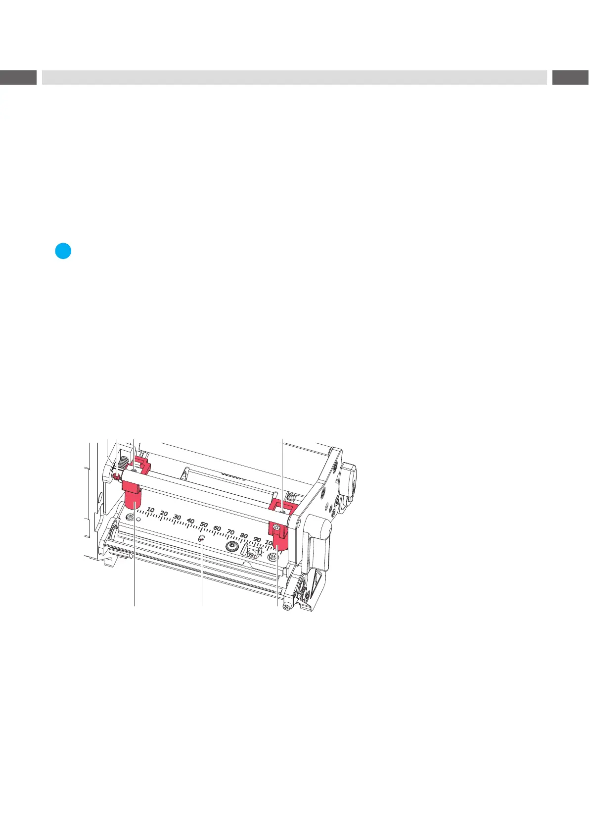
Figure 17 Preparing the printer for adjustment
1. Load labels and transfer ribbon which extend across the entire printing width
2. In the printer conguration, set the Print speed parameter to 100 mm/s.
3. Move the transfer ribbon deection to the central position (2) with the screw (1).
4. Position the plungers (4) in such a way that the adjustment screws are accessible through the holes (3) of the
square axis.
5. Loosen the screw (5) for the printhead bowing with an Allen key (1.5 mm) and turn it counterclockwise until turning
becomes perceptibly easier. This should occur after a maximum of a half a rotation.
 Loading...