SINT PCYC SUB.P
Call sub-program number
nonE; 1 to number
of programs
Soak time interval
Cont; 0.1 to 1400
(10) min
Program re-cycle count
Cont; 1 to 999
DER.S DI.SS NO.AL PROG LOCK SET.L
Derivative sensitivity
0.1 to 1.0 x dEr.t (0.5)
Display averaging
dir; 1 to 32 (6)
Disable -AL- alarm
display
; on
Disable program auto-exit
Auto; StAY
Security lock
nonE; LEV 3; LEV 2; ALL
Change program entry point
Off; on
USER-PROTECTED SETTINGS
LEVL 4
SP2 output device
none; SSd; rly; (read only)
Sensor burn-out
uP.SC; dn.SC; 1u.2d; 1d.2u
Zero adjustment
0.0 to 25% sensor
full scale
Set Monitor
Off; on
Read Monitor
VAr; hi; lo deg
Read Tune Data
CtA; Ctb; Ct1; Ct2; Ct3; Ct4;
oS1; uS; oS2
Software version
Consult unit
RESET
nonE; ALL
SP1.D SP2.D BURN REU.D REU.L SPAN ZERO CHEK READ TECH UER RSET
SP1 output device
none; rly; SSd; AnLG
Reverse outputs
1r.2d; 1d.2d; 1r.2r; 1d.2r
Reverse O/P LEDs
1n.2n; 1i.2n; 1n.2i; 1i.2i
Span adjustment
0.0 to 25% sensor
full scale
LEVL 3
CONFIGURE OUTPUT SAFETY SETTINGS CALIBRATION PERFORMANCE DATA
Read SP1 output %
0 to 100% read only
SP1 manual output %
0 to100% proportional
mode only
Limit SP1 output %
100 to 0%
Limit SP2 output %
100 to 0%
Main SP2 mode
nonE; dV.hi; dV.Lo; bAnd;
FS.hi; FS.Lo; Cool; EoP
Second SP2 mode
nonE; LtCH; hold; Lt.ho;
nLin
Display resolution
1 or 0.1 degree
Set scale maximum
0.0 Sensor max to sensor
full scale
Set scale minimum
0.0 Sensor min to sensor
full scale
Select input sensor
nonE
Select display units
nonE;°C; °F; bAr;
PSi; Ph; rH; SEt
\\
SP1.P HAND PL.1 PL.2 SP2.A SP2.B DISP HI.SC LO.SC INPT UNITLEVL 2
MANUAL ADJUSTMENTS SP2 MODES CONFIGURE INPUT
RANGING
TUNE BAND INT.T DER.T DAC CYC.T OFST SP.LK SET.2 BND.2 CYC.2LEVL 1
SP1 SETTINGS SP2 SETTINGS
Autotune or Park
Off; on; ParK; At.SP
SP1 Prop band (gain)/
hyst 0.1 deg to 100%
sensor f/s (10°C/18°F)
Integral time (reset)
Off; 0.1 to 60 min
(5 min)
Derivative time (rate)
Off; 1 to 200 sec
(25 sec)
Derivative approach
0.5 to 5.0 x bAnd
(1.5)
Cycle time or on/off
On.off; 0.1 to 81 sec
(20 sec)
Offset (manual reset)
0 to 50% x bAnd
(In.t = off)
Setpoint lock (SP1)
Off; on
Adjust SP2 setpoint
+/– sensor full scale or
full scale
SP2 prop band/Gain/
Hyst 0.1 deg to 100%
sensor f/s (2°C/3.6°F)
SP2 Cycle on/off
On.off; 0.1 to 81 sec
Program number
1 to 31
Run program
oFF; on; hoLd; dEL
inS; CoPY; PStE
Power failure
recovery mode
rSEt; Cont; hoLd
Program start value
PV; SP
Setpoint ramp time units
hour; 60s
Holdback value
oFF; 0.1 to 150
Event output (SP2A or SP3A)
nonE; 2d; 2E; 3d; 3E; 2d.3d;
2E.3d; 2d.3E; 2E.3E
PROG RUN FAIL ST.U SPRU SEG TYPE SPRR T.SP HB.V EO.PLEVL P
PROGRAMMER SETTINGS
S
egment number
1 to 126 max.
Define segment type
SPr; SoAK; StEP; LooP;
Call; EoP; dEL; inS
Setpoint ramp rate
1 to 9990 (100)
units/time
Adjust target setpoint
+/– sensor full scale or
full scale
Instrument address
0 to 255
Baud rate
1200; 2400; 4800
9600; 19k2
Data format
18n1; 18E1; 1801
TxRx activity
Off; on
ADDR BAUD DATA DBUCLEVL C
COMMS SETTINGS
High scale 1000
-1999 to 9999
Low scale 0
-1999 to 9999
Input high 50.0
0.1 to 50.0
Input low 10.0
0.0 to 49.9
Decimel 0000
000.0 or 00.00
Burnout SP3 - uPSC
dhSC
R
everse O/P3 3D
3r
AN.HI ANLO HI.IN LO.IN DECP SP3.A SP3.B SET.3 HYS.3 BRN.3 REV.3LEVL A
SP3 SAFETY SETTINGS
Main mode nonE
dv.hi; dVLo; bAnd; Fshi;
FSLo; EoP
Second mode nonE
LtCh; hoLd; Lt.ho
Set SP3 0
0 to 2500
Hysteresis SP3 20
1–100% sensor
full scale
SP3 ADJUSTMENTSSP3 MODESLINEAR SCALING AND INPUT SETTINGS
➔
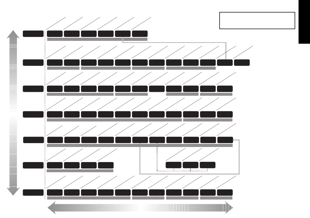
INITIAL
SET-UP
ENTRY
➔
PROGRAM ENTRY (DEFAULT)
Level C only visible
when COMMS
Option fitted
KEY ✱ ▼ OR ✱ ▲ TOGETHER TO CHANGE LEVELS OR OPTIONS
KEY ▼ OR ▲ TO VIEW FUNCTIONS
3
FUNCTIONS
MENU
Range of Adjustment shown
under description.
If applicable, factory settings
shown in bold.
For a full description of menu
functions refer to pages 7 to
10, and 16/17 in Programmer
section.
Note: The letter K appears in
the instrument display as the
character K
This page can be photocopied and
used as a visual aid and bookmark when
working in other parts of the manual.
!
English
 Loading...