S320 OCS Getting Started Guide
15 of 42
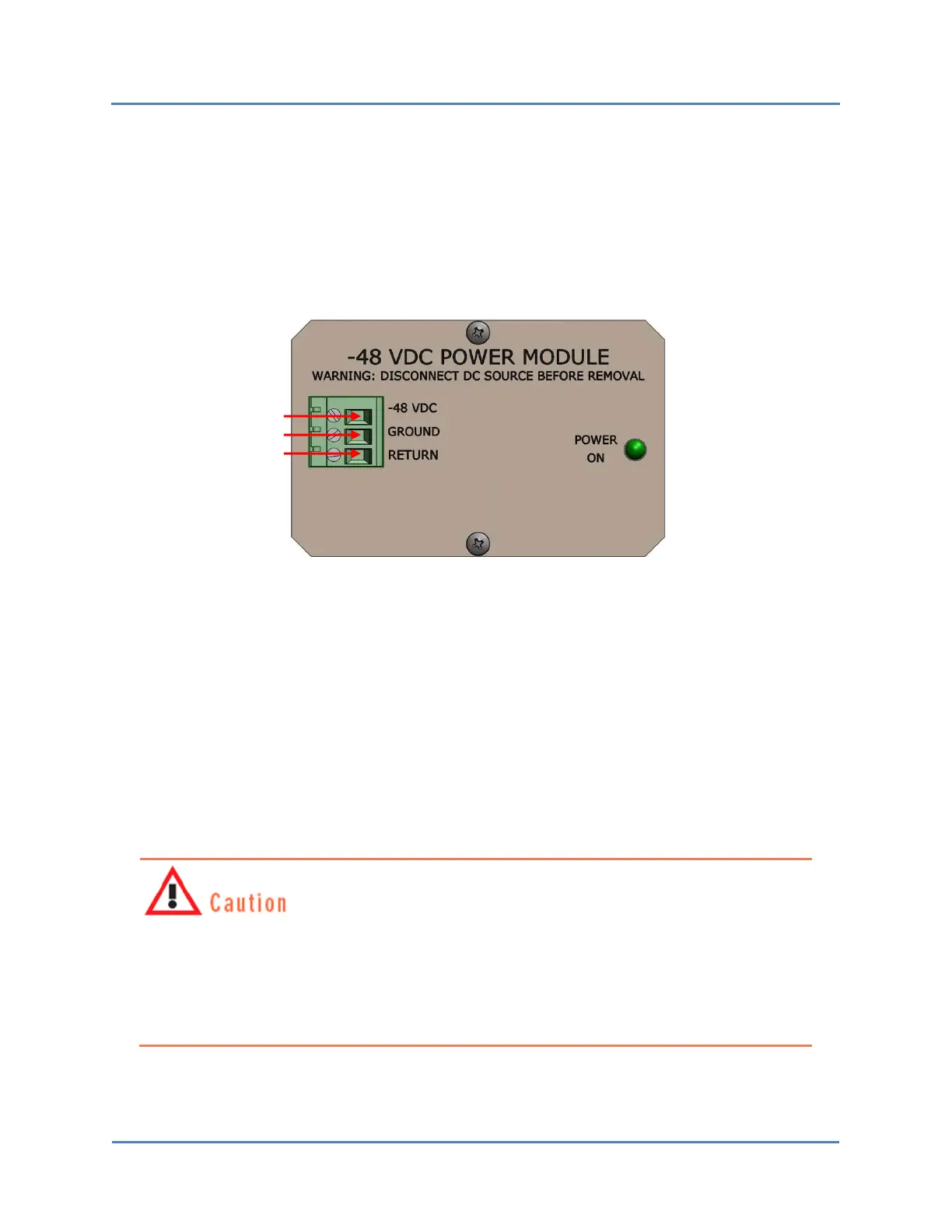
2. Insert one exposed end of each wire into the appropriate receptacle of the cam-over
terminal connector located at the left side of each power module on the S320 OCS.
As shown in Figure 7, the black (negative) cabling wire should be inserted in the
-48 VDC receptacle, the green-yellow (chassis ground) wire should be inserted in the
GROUND receptacle, and the red (positive) wire should be inserted in the RETURN
(+48 VDC) receptacle.
Figure 7 – S320 OCS Power Supply Connector
3. Secure each wire by tightening the screw beside each receptacle with a screwdriver.
Give each wire a light tug after securing it to ensure that it is firmly attached to the S320
OCS chassis.
4. Attach the remaining exposed end of each cabling wire to the appropriate terminal on
the power supply.
5. Activate both power sources—A (primary) and B (backup)—to deliver electrical power
to the S320 OCS.
To avoid possible injury to personnel and/or damage to the S320 OCS, make sure the
switch is properly grounded before powering up the system. CALIENT recommends
doing this by stripping one end of insulated copper wire and attaching it to one of the
two grounding screws located on the lower-right rear of the chassis (Figure 6), then
attaching the other end of the wire to a grounded circuit.
Black wire
Green-yellow wire
Red wire

 Loading...