EasyManuals Logo

CALIENT S Series Getting Started Guide

CALIENT S Series
42 pages
To Next Page IconTo Next Page
To Previous Page IconTo Previous Page
Page #38 background imageLoading...
Page #38 background image
S320 OCS Getting Started Guide
Doc. Part No. 460166-00
June 29, 2015
Rev. D10
38 of 42
3. Gently press the LC male connector into LC-UPC bulkhead female connector until it
locks in place.
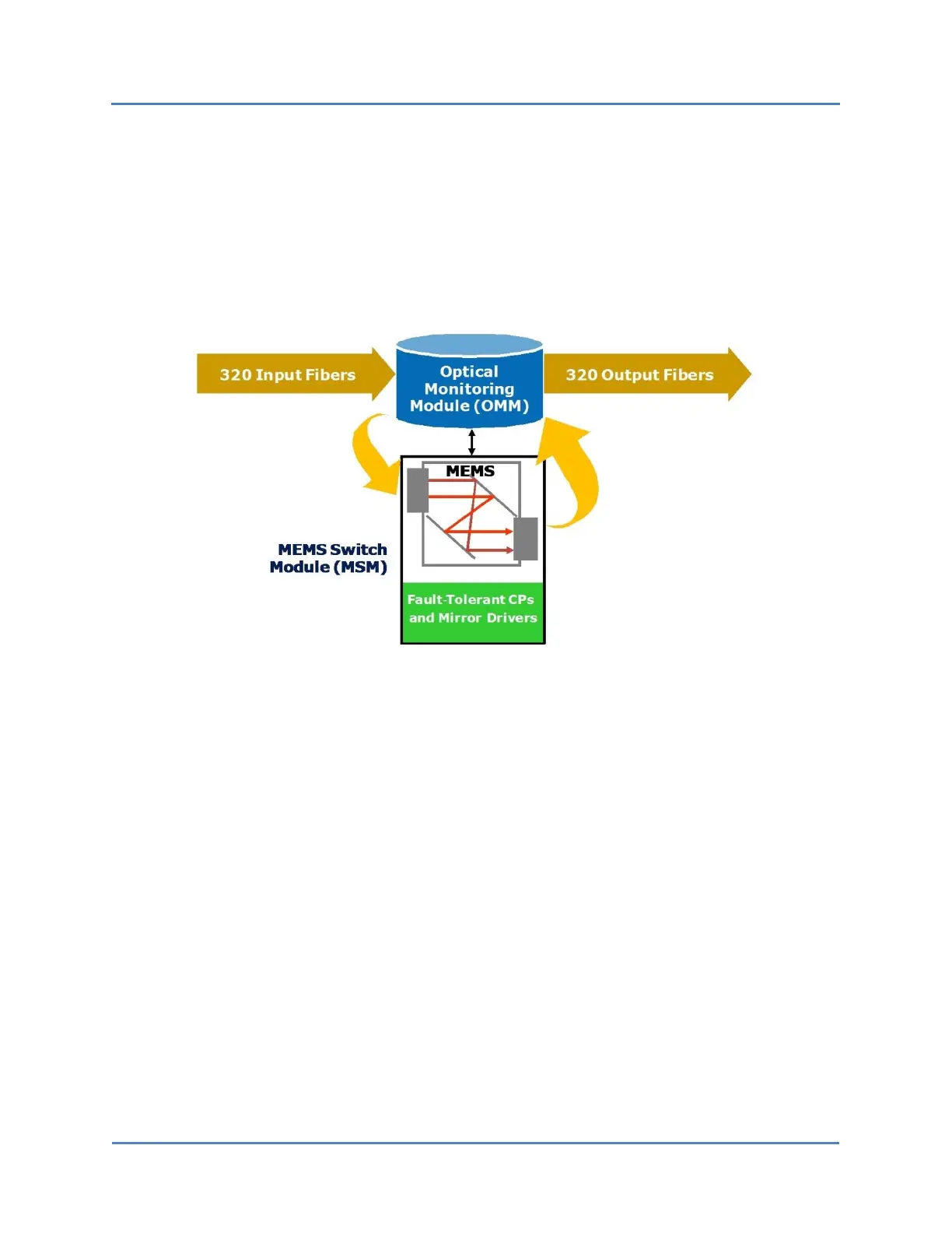
As Figure 11 illustrates, because of the directionality of the S320 OCS monitoring taps, the
switch operates with light transmitted from the input fiber terminations to the output fiber
terminations. Optical transmitters are connected to the inputs, and optical receivers are
connected to the outputs.
Figure 11 Fiber Direction

Table of Contents

Other manuals for CALIENT S Series

Questions and Answers:

Question and Answer IconNeed help?

Do you have a question about the CALIENT S Series and is the answer not in the manual?

CALIENT S Series Specifications

General IconGeneral
BrandCALIENT
ModelS Series
CategorySwitch
LanguageEnglish

Related product manuals