Page 7
Calorex Heat Pumps Ltd. · The Causeway, Maldon, Essex CM9 4XD, UK
Installation Manual
PPT8/12/16/22LX/LY SLIMLINE
SD638150 ISSUE 11
®
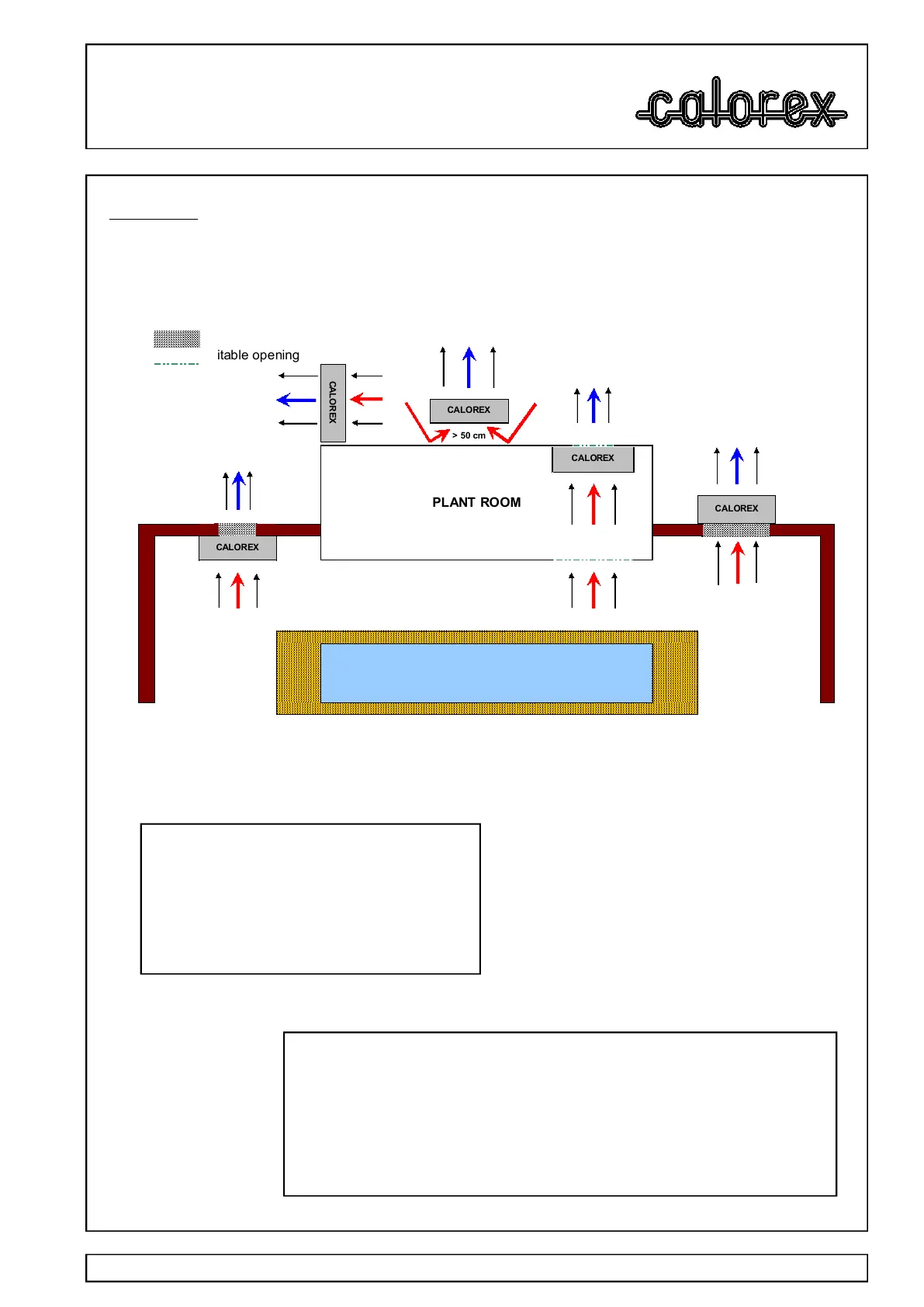
2.3 Air flow
Suitable opening
Suitable opening
> 50 cm
PLANT ROOM
WALL WALL
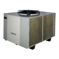
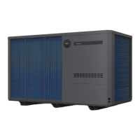
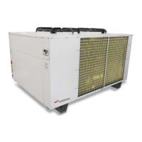
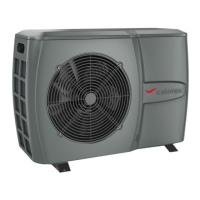
POSSIBLE POSITIONS OF A CALOREX HEAT PUMP
SWIMMING POOL/SPA
CALOREX
CALOREX
CALOREX
CALOREX
CALOREX
MODEL
Inlet Discharge
PPT8 0.157 0.168
PPT12 0.264 0.168
PPT16 0.322 0.173
PPT22 0.322 0.173
Minimum Free Area m²
TABLE 1
IMPORTANT
If multiple units are installed in an enclosed area then the inlet free areas
required for each unit can be added together to form one inlet aperture.
BUT discharge from each unit must be kept separate and must not be
incorporated into one common duct system.
Due consideration must be given to air flow i.e. do not obstruct inlet or outlet
and ensure discharge to air cannot recirculate to inlet. (See below).
Required Free Areas to provide air flow to and
from heat pumps when installed in an
enclosed area or where required to pass air
through a wall etc.
Free areas is the available area through which
air can pass through a grille or louvres.