- 19 -
Cont ...
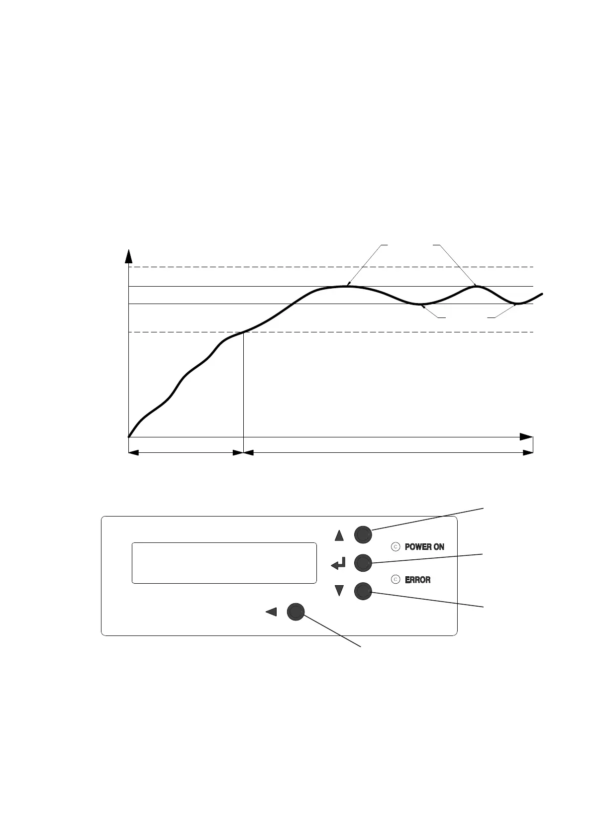
6.15 Controller overview
The controller is designed to be intuitive to use and allows functions and alarms
to be set by the installer/user. It also allows faults to be monitored and logged to
enable easier system fault diagnosis.
The functions are set using the 4 buttons (A, B, C & D) on the front of the
controller and with the help of on screen prompts via the back lit LCD display.
On the front of the unit a green ‘power on’ light will be displayed whilst the
unit is powered. If an alarm or error is raised the red ‘Error’ light will be displayed.
A number pressure set points can be set using the menus, these set points are
detailed below, 1 to 4 and in the description of the function.
Button A Scrolls up through menus or increases set values.
Button B Enters menus or selects values.
Button C Scrolls down through menus or reduces set values.
Button D Returns to previous menu
TIME
PRESSURE
HIGH ALARM SET VALUE (1)
LOW ALARM SET VALUE (4)
SYSTEM PRESSURE SET VALUE (2)
DIFFERENTIAL SET VALUE (3)
PUMP 'OFF'
PUMP 'ON'
SYSTEM FILL MODE
NORMAL OPERATION
S
YS
TE
M
P
R
E
S
S
U
R
E
Fig. 20
Fig. 21
A
B
C
D
 Loading...