- 7 -
Cont ...
2 LOCATION - GENERAL
2.11 Location: The preferred location of the unit is either on a solid wall
or on a smooth level floor, both of sufficient strength to support
the filled weight of the unit, close to the water source and a
suitable overflow position (see Section 9 - Technical Specification
for filled weight). The unit must not be installed in a loft space.
It must also be considered that the noise and vibration from
the unit may be transmitted through the structure it is sited on.
Ensure the minimum clearance requirements are followed to allow
servicing of the unit
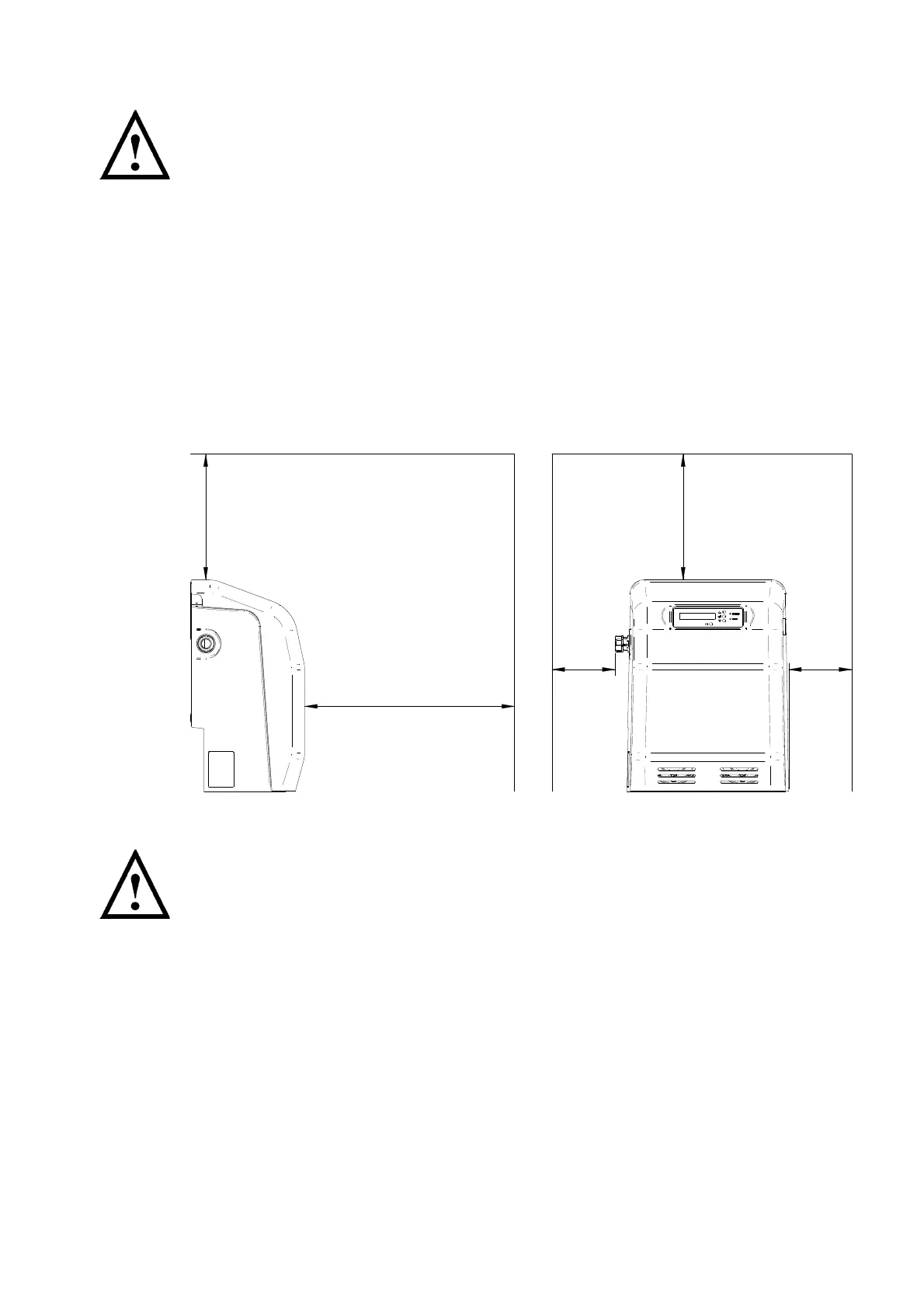
2.12 Access and minimum clearance requirements: For emergencies
and maintenance the unit must be easily accessible and have the
minimum clearance around it as laid out in Fig. 2. Additional access to
the front of the unit will be required to operate the keypad and view
the display.
2.13 Protection: The unit must be located in a dry, frost free area.
2.14 Ventilation: Ensure an adequate air flow to cool the unit.
Separate the unit from other appliances that generate heat. Do not
block the vent holes on the front cover or the air inlet at the rear.
2.15 Water retention: Site the unit in a location where in the unlikely event
of a water leak, any spillage is contained or routed to avoid electrics
or areas sensitive to water damage. As part of the AB airgap (CAT 5
fluid isolation) the tank has a weir type overflow on the right hand side,
water will be discharged from this area in the event of the failure of the
inlet valve or non-return valves.
2.16 Supply inlet pressure: The water supply inlet pressure must not exceed 7 bar.
2.17 Ambient temperature: The unit must be sited in a location where the ambient
temperature does not drop below 4 °C or exceed 40 °C.
Fig. 2
300
500
300
150150
 Loading...