Do you have a question about the CAME BPT DC-DVC/IP ME and is the answer not in the manual?
States compliance with directives and provides guidance on decommissioning and disposal.
Details the connections and signals for terminal boards 1 and 3.
Explains the function of CN2/CN4 connectors and the meaning of status messages.
Specifies the maximum distance for installations powered by a PoE switch.
Details cable lengths and device counts for locally powered setups.
Instructions on how to access the device's web interface and log in modes.
Displays device technical characteristics, hardware and software versions, and SIP account status.
Configuration of network parameters like IP address, Netmask, and Gateway.
Configuration of SIP user name, password, server IP, and account status.
Explains how to view and set up call key configurations for panels.
Details how to view and select contacts from the call list for communication.
Lists and provides details for extensions associated with contacts on the network.
Covers firmware updates and password modification for device maintenance.
Explains how to generate and save statistics and log files for troubleshooting.
Describes creating a system structure and configuring IP Entry Panels using PCS Xip software.
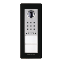
This document outlines the configuration and operational aspects of the DC-DVC/IP ME device, an entry panel designed for integration into a broader Xip system, typically managed via PCS Xip software. The manual provides comprehensive instructions for installation, connection, and software-based configuration, ensuring proper functionality within an interconnected security and communication network.
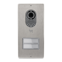
The DC-DVC/IP ME device serves as an entry panel, facilitating communication and access control within a building or complex. It supports both video (DVC/IP) and audio-only (DC-IP) functionalities, depending on the specific model and configuration. The device integrates with a central server, allowing for advanced features such as programmable relays for door lock release, contact inputs for door open status, and system outputs for various control applications.
The entry panel is equipped with a set of call keys, which can be configured to dial specific internal units or extensions. These call keys are customizable, allowing for flexible assignment of contacts and extensions. The device also supports additional push-button panels, expanding its capacity for calls and interactions.
For access control, the device can be connected to an access control module, which may include a keypad, RFID reader, or a combined keypad/display/RFID unit. This allows for secure entry through various authentication methods. The device also features a solenoid lock output, enabling direct control over door locking mechanisms.
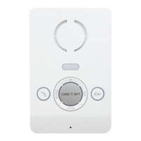
The system incorporates visual feedback through LED indicators. A PROG LED provides status updates, indicating whether the device is off, flashing slowly (suggesting a call in progress or system busy), or flashing quickly (indicating an active conversation or door open status). These visual cues help users understand the device's current state.
The device operates on a 12-24 V DC power supply and can also be powered via Power over Ethernet (PoE) for simplified installation and reduced cabling requirements. Ethernet connectivity is crucial for its integration into the IP network, allowing for remote configuration and data exchange with the central server.
The DC-DVC/IP ME device is designed for user-friendly interaction, primarily through its call keys and integrated display/keypad (if present). When a visitor presses a call key, the device initiates a call to the pre-configured internal unit. The PROG LED provides immediate visual feedback on the call status, changing from off to flashing slowly (call in progress) and then to flashing quickly (conversation in progress or door open).
For residents or authorized personnel, the device offers various methods for door release. This can be achieved through a dedicated door lock release button connected to the device, or via the access control module using a keypad code, RFID tag, or other integrated authentication methods. The system also supports a door open contact input, which can be used to monitor the status of the door and trigger alarms if the door remains open for an extended period.
The device's configuration and management are primarily performed through a web interface, accessible via a standard web browser (Chrome, Firefox, Safari). This interface allows installers and administrators to set up network parameters, configure call keys, manage SIP accounts, and update firmware. The web interface is structured into several sections, including System Info, Network, SIP, Panel, Calls list, Maintenance, and Diagnostic, each providing specific configuration options.
The "System Info" section provides an overview of the device's characteristics, including hardware and software versions, and the SIP account status. The "Network" section allows for the configuration of IP addresses, subnet masks, and gateways, supporting both static IP assignment and DHCP (for future uses). The "SIP" section is crucial for setting up the device's SIP user name, password, display name, and the IP address of the SIP server, ensuring proper communication within the VoIP system.
The "Panel" section enables the configuration of the entry panel's call keys, allowing administrators to assign specific contacts to each button. If an additional push-button panel is connected, its call keys can also be configured in this section. The "Calls list" section displays all units that can be called by the entry panel, and administrators can select a contact to view or modify its details, including associated extensions.
The device also supports advanced features such as "Dusk notified by," which can be configured to trigger actions based on ambient light conditions, and "Aux. lift management," indicating potential integration with elevator control systems. These features enhance the device's utility beyond basic communication and access control.
Maintenance of the DC-DVC/IP ME device primarily involves firmware updates and diagnostic checks, both of which are managed through the web interface. The "Maintenance" section of the web interface allows administrators to update the device's firmware. This process involves pressing the "LOAD" button, selecting the firmware file from a computer, and initiating the update. The access password for this section can also be changed for security purposes. Regular firmware updates are essential to ensure the device operates with the latest features, security patches, and performance improvements.
The "Diagnostic" section provides tools for troubleshooting and monitoring the device's operation. This section includes "STATISTICS," which offers statistical data on the device's performance, and "LOG FILES," which allows for the generation of data files useful for technical service. Administrators can choose the "LOG LEVEL" to specify the accuracy and type of log files to be generated. Log files can be saved in various locations: "Local-RAM" (temporary memory), "Local-FLASH" (internal memory with limited capacity), or remotely on a specified server. The ability to save log files remotely is particularly useful for centralized monitoring and troubleshooting in larger installations.
Before performing any cleaning or maintenance operations, it is crucial to disconnect the device from its power supply to prevent electrical hazards. The equipment is designed for a specific purpose, and any use outside of its intended function is not supported by the manufacturer. Installation, programming, commissioning, and maintenance should only be carried out by qualified technicians who are properly trained and adhere to all relevant regulations, including health and safety measures.
The device is also designed with environmental considerations in mind. At the end of its life cycle, the device and its packaging materials should be disposed of in compliance with local regulations, rather than being discarded in the environment. Recyclable components are marked with a symbol and material ID for proper recycling.
| Communication Protocol | IP |
|---|---|
| Audio Codec | G.711 |
| Video Codec | H.264 |
| Mounting | Surface |
| Housing Protection Rating | IP54 |
| Camera Resolution | 720p |
| Network Interface | Ethernet |
| Supported Protocols | SIP, RTSP |