6 09/2014
© CAME cancelli automatici S.p.A. - The data and information reported in this installation manual are susceptible to change at any time and without obligation on CAME cancelli automatici S.p.A. to notify users.
ENGLISH
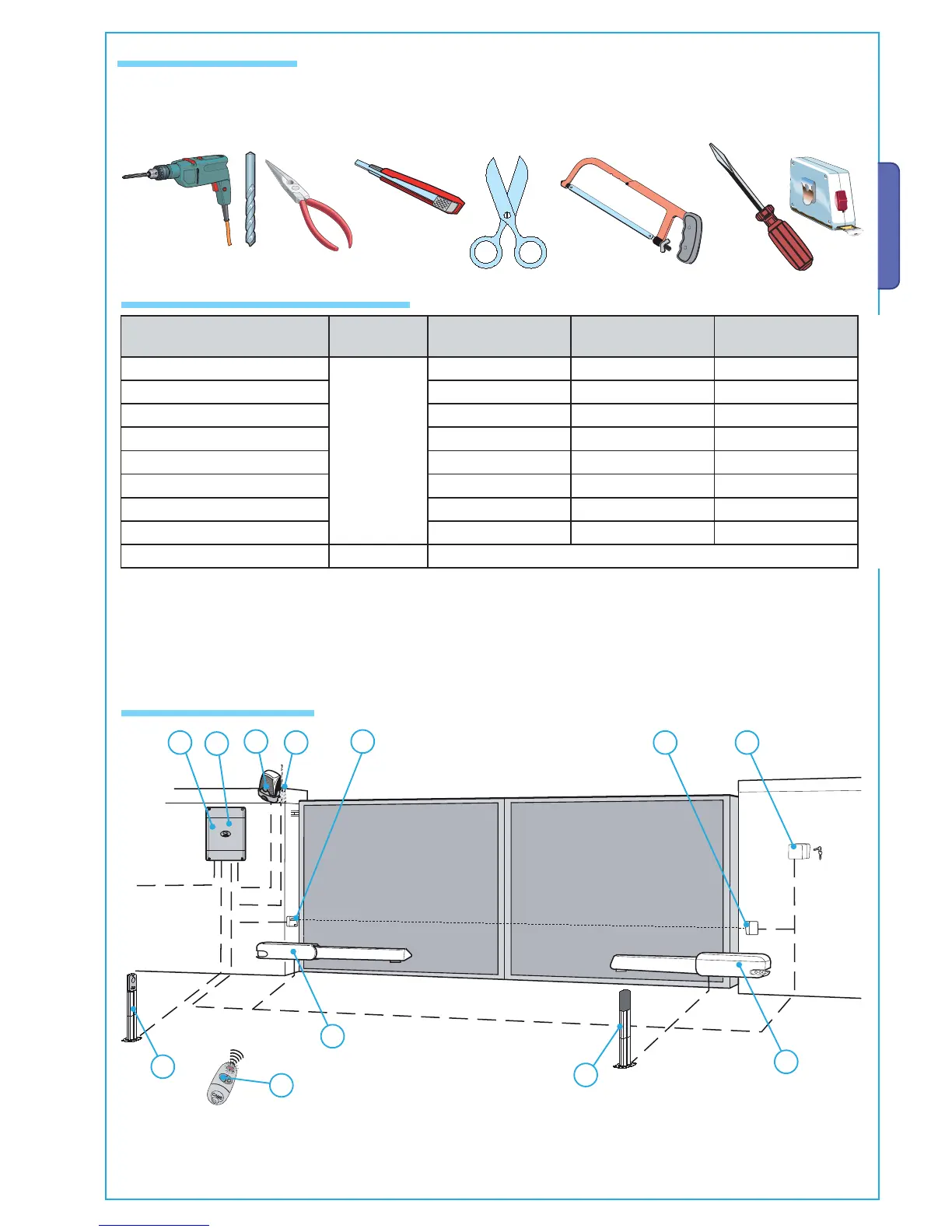
5.2 Tools and materials
Make sure you have all the tools and materials you will need for the installation at hand to work in total safety and compliance
with the current standards and regulations.
N.B.: The cable section, with di erent lengths from those shown on the table, must be considered on the basis the actual draw of the
connected devices, according to what is prescribed in the CEI EN 60204-1 Code.
For connections that require varying loads on the same line (i.e. sequential), the table values should be reconsidered depending on
the actual draws and distances.
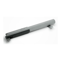
5.3 Cable list and minimum thickness
Connections Type of cable
Length of cable
1 < 10 m
Length of cable
10 < 20 m
Length of cable
20 < 30 m
Control panel power supply 230V
FROR CEI
20-22
CEI EN
50267-2-1
3G x 1,5 mm
2
3G x 2,5 mm
2
3G x 4 mm
2
Motor power supply 230V 4G x 1 mm
2
4G x 1,5 mm
2
4G x 2,5 mm
2
Flashing light 24V 2 x 0,5 mm
2
2 x 1 mm
2
2 x 1,5 mm
2
Photocell transmitters 2 x 0,5 mm
2
2 x 0.5 mm
2
2 x 0,5 mm
2
Photocell receivers 4 x 0,5 mm
2
4 x 0,5 mm
2
4 x 0,5 mm
2
Accessories power supply 24V 2 x 0,5 mm
2
2 x 0,5 mm
2
2 x 1 mm
2
Control and safety devices
2 x 0,5 mm
2
2 x 0,5 mm
2
2 x 0,5 mm
2
Endpoints 3 x 0,5 mm
2
3 x 1 mm
2
3 x 1,5 mm
2
Antenna connection RG58 max. 10 m
1) Gearmotor
2) Control panel
3) Radio receiver
4) Photocells
5.4 Standard installation
5) Keyswitch
6) Antenna
7) Flashing light
8) Transmitter