".
!
"#$
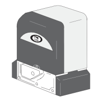
6.3 Description board BN1
1 - ZBX241 board connecting terminal board
2 - The green LED indicator light signals mains power supply on
3 - The red LED indicator light signals emergency battery power supply on
3
1
2
9
All the data and information contained herein is considered subject to change at any time and at our discretion
ENGLISH
••• •
,).%
&53%!
FC
F
M
FA
N
• • • • • • • • • • • • •
+ T.P.A. -
• • • • • • • • • • • • • • • • • • • • • • • • • • •••••••••••••••••••• • • • • • • • • • • • • • • • • • • • • • • • • • • • • • •
••••••••• • • • •• • •
10 11 E1 1233P C1 C3 7
24V
AC
+
-
L1T
L2T
L1
L2
BATTERY
D
C
B
A
+ T.A.C. -
+ SENS. -
PROGRAM.
CH1
?
?
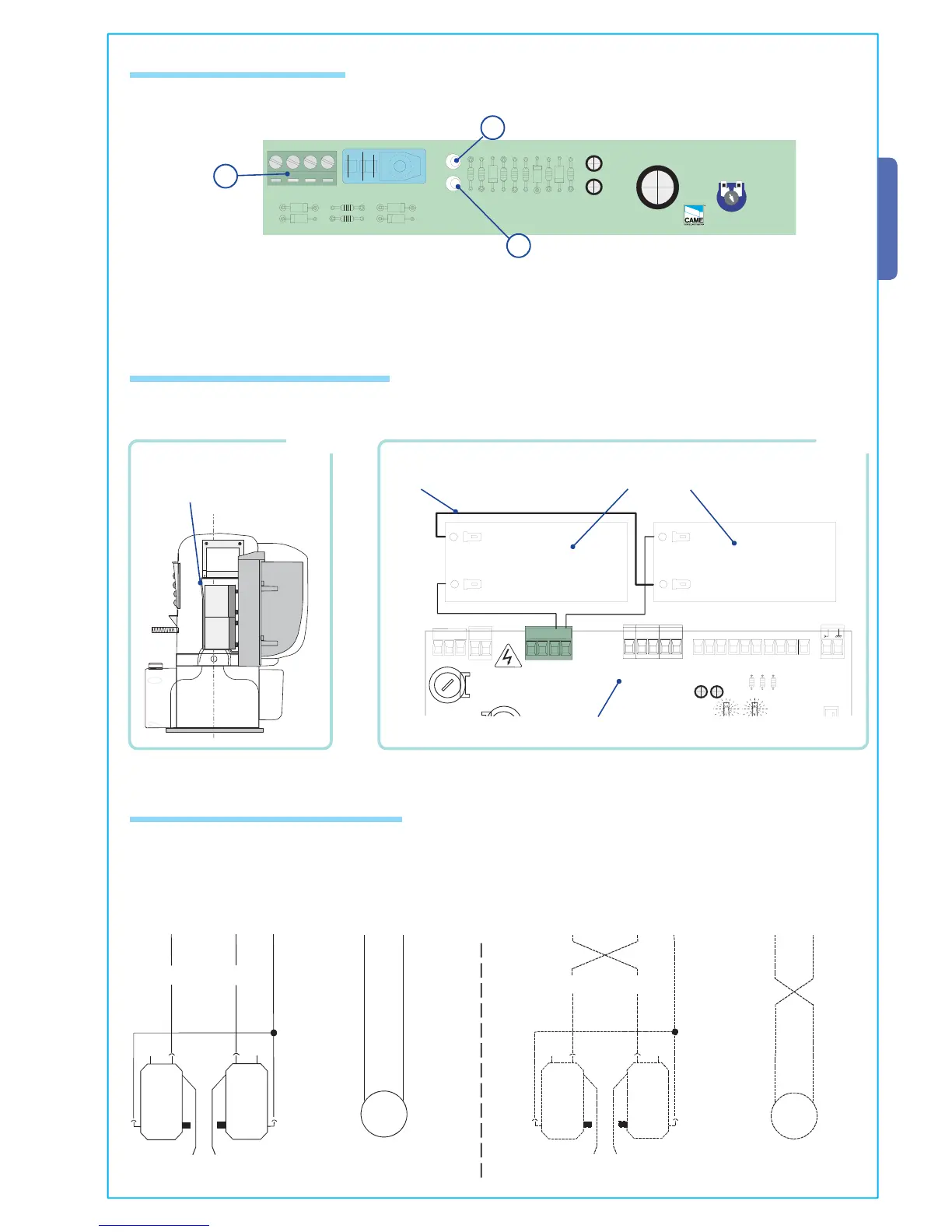
6.5 Gearmotor end-stop connection
FA FC F M N
NC NC
M
FA FC F M N
NC NC
M
6.4 Emergency battery connection
Limit switch unit 24V (d.c.) single-phase motor Limit switch unit
The motor and limit switch unit are wired at the factory for mounting on the left-hand side of the gate (as seen from the inside).
If right-hand installation is desired:
- invert limit switch connections FA-FC on the terminal block;
- invert motor phase connections M-N on the terminal block.
24V (d.c.) single-phase motor
Insert batteries in the appropriate bracket (Fig.1) and connect them (using the cables provided) to the ZBX241 board (Fig.2)
terminal (+,-).
12V - 1.2 Ah emergency batteries
NOT INCLUDED
Bridge connection
lead
FIG.1
Battery bracket
FIG.2
The BN1 board allows the automation to be battery operated in case of a power outage. When power is restored, the card also
recharges the batteries.
ZBX241 board
 Loading...