6
1
2
1
2
4
5
3
FASE
PHASE
PHASE
PHASE
6
ETAPA
FASE
FASE
PHASE
PHASE
PHASE
7
ETAPA
FASE
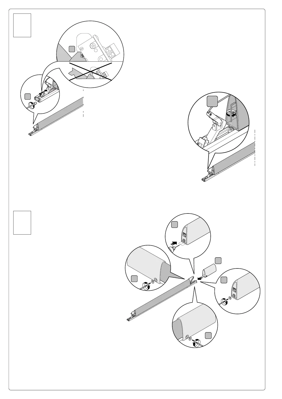
Regolare la tensione della fune sul meccanismo attraverso la vite di
regolazione (fase.6 fig.1) e verificare il corretto azionamento del
microinterruttore del contatto N.C. con un tester. Fissare il grano (vite senza
testa) per bloccare il meccanismo (fase.6 fig.3).
Adjust the cable tension on the mechanism with the adjusting screw (phase 6 fig.1)
and use a tester to check that the N.C. contact microswitch switches correctly.
Tighten the grub screw (screw without head) to secure the mechanism (phase 6
fig.3).
Régler la tension du câble sur le mécanisme à l’aide de la vis de réglage
(phase 6 fig. 1) et vérifier si le microinterrupteur du contact N.F. s’actionne
correctement avec un testeur. Fixer la vis sans tête pour bloquer le mécanisme
(phase 6 fig. 3).
Mit Hilfe der Einstellschraube die Seilspannung auf dem Mechanismus (Phase 6
Abb. 1) regulieren, und mit einem Tester den korrekten N.C. Kontakt -
Mikroschalterantrieb überprüfen. Zur
Blockierung des Mechanismus den Stift
(Schraube ohne Kopf) befestigen. (Phase 6 Abb. 3).
Regule la tensión del cable en el mecanismo a través
del tornillo de regulación (etapa 6 fig.1) y controle el
accionamiento correcto del microinterruptor del
contacto N.C. con un tester. Apriete el tornillo sin
cabeza para bloquear el mecanismo (etapa 6 fig.3).
Stel de spanning van de kabel in op het mechanisme
met behulp van de stelschroef (fase 6 fig.1) en controleer
de werking van de microschakelaar van het contact
N.C. (normaal gesloten) met een tester. Plaats de stift
(wormschroef) zodat het mechanisme geblokkeerd wordt
(fase 6 fig.3).
Solo su istallazioni verticali forare con punta Ø 4 le apposite tracce situate
sul tappo da posizionare nella parte inferiore (fase.7 fig. 1) della costa,
per evitare che si formi condensa all'inerno. Inserire il tappo e fissarlo
con n°3 viti UNI 6954 Ø 3,9 x 13 e relative rondelle (fase.7 fig.3-4-5)
(vedi pag. 4 fig. A).
On vertical installations only, use a 4-Diam. bit to drill the
appropriate traces on the top that must be
positioned in the lower part (phase 7 fig. 1) of
the rib; this avoids condensation from building
up inside. Insert the top and secure it with
3 UNI 6954 screws DIA 3.9 x 13 and
related washers (phase 7 fig.3-4-5) (see
page 4, fig. A).
Uniquement pour les installations
verticales: percer le bouchon à placer dans
la partie inférieure (phase 7 fig. 1) du bord
sensible aux endroits indiqués avec une mèche
Ø 4, pour éviter qu’il se forme de la condensation
à l’intérieur. Mettre le bouchon et le fixer avec 3 vis
UNI 6954 Ø 3,9 x 13 et les rondelles correspondantes
(phase 7 fig. 3-4-5) (voir à la page 4 fig. A).
Zwecks Vermeidung von innerer
Kondenswasserbildung , ausschließlich
bei vertikalen Installationen mit einer
Spitze Ø 4 den im unteren Teil des Steges
anzubringenden Verschluß an den eigens
dafür vorgesehenen Stellen durchbohren (Phase 7 Abb. 1). Den
Verschluß einführen und mit 3 Schrauben UNI 6954 Ø 3,9 x 13 und
den entsprechenden Unterlegscheiben (Phase 7 Abb. 3-4-5) (siehe
Seite 4 Abb. A) befestigen.
Sólo en las instalaciones verticales, taladre con una broca de Ø 4 en las
marcas situadas en el tapón a colocar en la parte inferior (etapa 7 fig. 1) de la
goma, para que no se forme condensación en su interior. Coloque el tapón y fíjelo
con 3 tornillos UNI 6954 Ø 3,9 x 13 y sus arandelas correspondientes (etapa 7 fig.3-4-5) (véase pág. 4
fig. A).
Enkel in geval van verticale plaatsing moet een gat geboord worden met een boorpunt met Ø 4 ter hoogte
van de merktekens op de dop die onderaan op de ribbe geplaatst moet worden (fase 7 fig. 1), om te
vermijden dat er binnenin condens gevormd wordt. Plaats de dop en bevestig hem met de 3 schroeven
UNI 6954 Ø 3,9 x 13 en bijbehorende ringetjes (fase 7 fig.3-4-5) (zie pag. 4 fig. A).
 Loading...