Do you have a question about the CAME PXC2-32 and is the answer not in the manual?
Explains symbols used in the manual for safety and important information.
Details the intended application of the security alarm control units.
Outlines the terms of the product warranty and manufacturer's liability.
Crucial rules for safe installation, operation, and maintenance of the system.
Illustrates the network and device connections for the security system.
Lists the detailed technical specifications of the PXC2 series control units.
Depicts the standard linear connection of devices on the RS-485 bus.
Illustrates a branched wiring configuration for the RS-485 bus.
Shows a double-branch wiring configuration for the RS-485 bus system.
Illustrates RS-485 bus wiring utilizing a bus amplifier for extended reach.
Provides practical guidelines and considerations for RS-485 bus wiring.
Guides on selecting appropriate cable cross-sections based on distance and power draw.
Explains input connection methods and use of balancing resistors.
Shows various diagrams for connecting different types of input sensors.
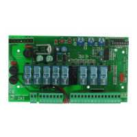
Identifies the key physical components located on the control unit's board.
Details the unit's electrical parameters and physical dimensions.
Identifies and explains the function of PCB components and connectors.
Explains the functions of the dip switches for system configuration.
Describes various connectors like Ethernet, USB, and SD Card slots.
Explains the purpose and operation of the control unit's reset button.
Identifies the terminal for connecting the main power supply.
Explains the meaning of each status LED on the control unit for operational feedback.
Provides guidance for physically installing the control unit on a wall.
Details the procedure for connecting the 230V AC mains power to the unit.
Explains how to connect the backup battery and lists associated safety warnings.
Lists compatible battery types and their current delivery capabilities.
Describes the installation process for tamper-proof switches.
Explains how control unit outputs can be programmed as inputs or outputs.
Details the specific functions and operation of alarm relays 1, 2, and 3.
Illustrates how to connect both self-powered and non-self-powered sirens.
Provides instructions for physically mounting the keypads.
Explains the process for assigning unique addresses to keypads.
Describes how to read and understand the messages displayed on the keypad.
Explains system status icons and LED indicators on keypads and readers.
Details how system status can be displayed or masked for privacy.
Describes the functions of buttons on alphanumeric keypads for operation.
Guides users on accessing and navigating the keypad's internal menu.
Lists the various settings and options available within the keypad's menu.
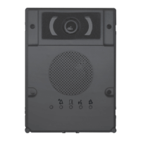
Explains the PXITU01 key reader's role in managing the alarm system with keys.
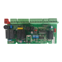
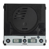
Identifies the main components on the PXITU01 key reader circuit board.
Explains how LEDs on the key reader indicate the system's current status.
Provides specific instructions for installing the PXITU01 key reader.
Details the PX4IOR expansion module with four configurable connection points.
Explains how to set addresses and configure DIP switches for the PX4IOR module.
Lists the technical data and specifications for the PX4IOR module.
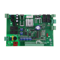
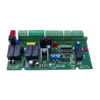
Identifies the components and connectors on the PX4IOR module board.
Provides guidance for installing the PXWRX01 wireless receiver in a suitable environment.
Lists the technical data and specifications for the PXWRX01 wireless receiver.
Explains how to set the address for the PXWRX01 wireless receiver.
Describes the PXONV module for integrating cameras with Onvif protocol.
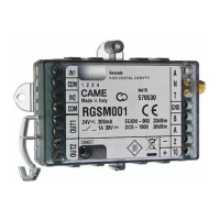
Details the PXMC3G module for GSM/UMTS communication and SMS/voice messages.
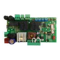
Identifies PXMC3G components and explains the meaning of its status LEDs.
Explains the steps for fitting and removing the SIM card from the PXMC3G module.
Provides instructions for installing the PXMC3G module into the control unit.
Identifies the components and parts of the PXTEL01 PSTN dialler board.
Explains the meaning of the LED indicators on the PXTEL01 dialler.
Lists the technical data and specifications for the PXTEL01 PSTN dialler.
States the device's compliance with relevant EU directives and product regulations.
Provides guidance for responsible dismantling and disposal of the product.
| Brand | CAME |
|---|---|
| Model | PXC2-32 |
| Category | Control Unit |
| Language | English |