❼
⓰
⓰
⓫
⓭
❽
❿
❾
⓯
❻
⓮
❶
❶
❷ ❸
❹
❺
⓬
Page
13 - Manual FA01869-EN - 08/2022 - © CAME S.p.A. - The contents of this manual may be changed, at any time, and without notice. - Translation of the original instructions
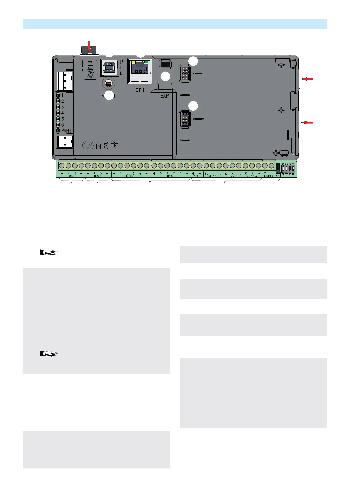
Board description
❶
RS485 BUS
RS-485 bus terminals for connecting keypads, remote mod-
ules and key readers.
[+,-] bus power-supply.
[A,B] data.
[F6] for PXC2-32: 0.75 A self-resetting fuse
[F6] for PXC2-64: 1.1 A self-resetting fuse
[F6] for PXC2-212: 1.5 A self-resetting fuse
PXC2-32 has only one RS485 BUS while PXC2-64
and PXC2-212 have two RS485 BUSes
❷
Connection Points
Control unit connection points, can be inputs of NO, NC, SB,
DB, TB, CI type or outputs.
[+,-] power supply.
[1, 2, 3, 4, 5, 6, 7, 8] If set as inputs.The reference is at
negative.
If they are set as outputs they are open collector outputs pro-
grammable to negative and protected by a 100 ohm resistor
(ON = 0 Vdc, OFF = NO).
[F3] for PXC2-32: 0.75 A self-resetting fuse
[F3] for PXC2-64: 1.1 A self-resetting fuse
[F3] for PXC2-212: 1.5 A self-resetting fuse
A short circuit with open collector output active for
a prolonged time can lead to the protection resistance failure
❸
Control unit output terminals.
[AUX +, -] power supply available in output protected by
self-resetting fuse F5.
[NO, C, NC] relay 1, General alarm relay with dry contacts
[NO, C, NC] relay 2-3, Programmable relay with dry contacts
[F5] for PXC2-32: 1.1 A self-resetting fuse
[F5] for PXC2-64: 1.1 A self-resetting fuse
[F5] for PXC2-212: 1.5 A self-resetting fuse
❹
Tamper
[T, +] terminals for the control unit tamper connection.
[JP1] jumper to enable / disable the tamper (position C to
disable the control unit tamper, position O to enable it). For
additional details, see the TAMPER chapter.
❺
DipSwitch
Dip 1 is used to set the control unit from service to maintenance
(ON = Maintenance, OFF = Service)
Dip 2 is used to reset the Codes and Keys to the factory value.
Dip 3 is used to reset the parameters to the factory value
Dip 4 is used to enable the control unit firmware programming
❻
PXMC3G
[CN1] Connector for PXMC3G module
❼
PXTEL01
[CN2] Connector for PXTEL01 module
❽
Additional modules
[CN3] connector for the PXONV connection module.
❾
Ethernet connector
Ethernet connector for connection to the local LAN network
❿
USB Device Connector
USB Device connector for programming through PXC2-Man-
ager
⓫
SD Card Slot
Slot for installing an SD card for storing CCTV camera videos
⓬
Reset button
[P1] button to restart the control unit (it is not used to restore
parameters; it does not modify the configuration).
Short press: system reset software. The system restarts
maintaining all the statuses unchanged
Long press (more than 5s): system hardware reset. The sys-
tem restarts and all internal statuses are reset. Equivalent
to completely shutting down the system (battery + network)
⓭
Power supply
[Vac] Power supply connection connector