08:24 19/03/13
#####UUUPX---
08:24 19/03/13
#####UUUPX---
08:24 19/03/13
#####UUUPX---
➡
08:24 19/03/13
#####UUUPX---
❷
❶
❹
❸
❺
Page
18 - Manual FA01869-EN - 08/2022 - © CAME S.p.A. - The contents of this manual may be changed, at any time, and without notice. - Translation of the original instructions
Keypads - PXKTB02/PXKTN02
Capacitive "Flat" black (PXKTN02) or white (PXKTB02) keypads con-
nectable on Bus. Wall or flush mounted.
TYPE B ACE device, EN50131 GRADE 3 certified (
).
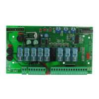
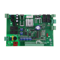
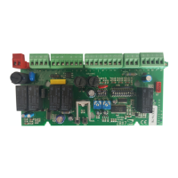
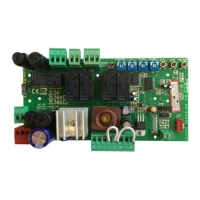
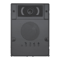
BOARD DESCRIPTION
PXKTN02
PXKTB02
❶
RS-485 bus terminals for connecting keypads and key readers:
[+,-] bus power supply;
[A,B] data
❷ Terminals 1,2 : Connection points
❸ Anti-opening / anti-tear tamper.
❹ Red LED signalling communication on the bus. If it flashes it
means that the keypad communicates with the control unit
❺ Keypad buzzer.
In compliance with EN50131, after 5 invalid attempts to access the
keypad using the PIN, access is blocked for 100 seconds.
After 21 invalid attempts, the system generates a device tampering
alarm.
INSTALLATION
The keypads must be installed on the wall in sheltered, raised or
recessed areas with an OPALESI box (PXWKTN01/PXWKTB01 only).
Connect the control unit and keypads to the respective terminals [+
A B -].
ADDRESSING
The keypad addressing is performed directly on the keypad through
the local menu.
KEYPAD DISPLAY
The display is made up of 2 rows of 16 characters each. The keypad
in stand-by goes in “Energy saving” mode decreasing its light inten-
sity after a set time.
Under the display there are 16 numbers which make it easier to in-
terpret the second row of the display. Its key for understanding is:
# = area on;
U = area in turning-on phase (output time counting in progress);
X = area turning on but not ready for arming because there are open
inputs;
P = area partially on (there is at least one input associated to the
area temporarily disabled);
A = area in alarm status;
R = area in active patrol function;
N = area disabled not ready
- = area off;
= area not managed by the keypad.
Example: readin
g of display represented:
• Managed areas: 1, 2, 3, 4, 5, 6, 7, 8, 9, 10, 11, 12, 13.
• Unmanaged areas: 14, 15, 16.
• On areas: 1, 2, 3, 4, 5.
• Area in turning-on phase: 6, 7, 8.
• Areas partly on. 9.
• Area not ready: 10.
• Areas off: 10, 11, 12, 13.