Page
14 - Manual FA01869-EN - 08/2022 - © CAME S.p.A. - The contents of this manual may be changed, at any time, and without notice. - Translation of the original instructions
⓮
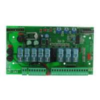
Status LED
Status LED for checking the correct operation of the security
control unit
LED1 green:
-
the system is off
-
the system is in operation
-
during initialization
LED2 red:
-
Communication with RS485 BUS peripherals
LED3 green:
-
battery not installed or discharged
-
battery charged
LED4 red:
-
configured system
-
system in peripheral configuration (at start-up or after
exiting the technical menu)
Led5 green:
-
inactive telephone indications
-
telephone indications in progress (both outgoing and
incoming)
Led6 red:
-
no connection to Came Connect
-
system connected to Came Connect
-
device connected remotely
Led7 Green:
-
unpowered system
-
powered system
Wall-mounting
PXC2-32/PXC2-64 PXC2-212
Install the control unit in a place away from access points and difficult to identify.
Fix on a wall suitable to sustain the control unit over time.
Prepare the holes and channel for cable passage before installation.
Use the 4 holes for fixing to the wall and use 6 x 30 mm plugs with screws 4.5 x 40 mm or higher.
The control unit must be installed at a maximum height of 2m.
⓯
Battery
[Vbat] Battery connection connector.
⓰
USB Host Ports
USB host ports for connecting the WiFi dongle and for updat-
ing the control unit and peripherals on the 485 bus through
USB key.
 Loading...