www.came.co.uk Helpline Tel: 0870 012 9000 - 2 -
DIR
Rx
12v
24v
Voltage
jumper
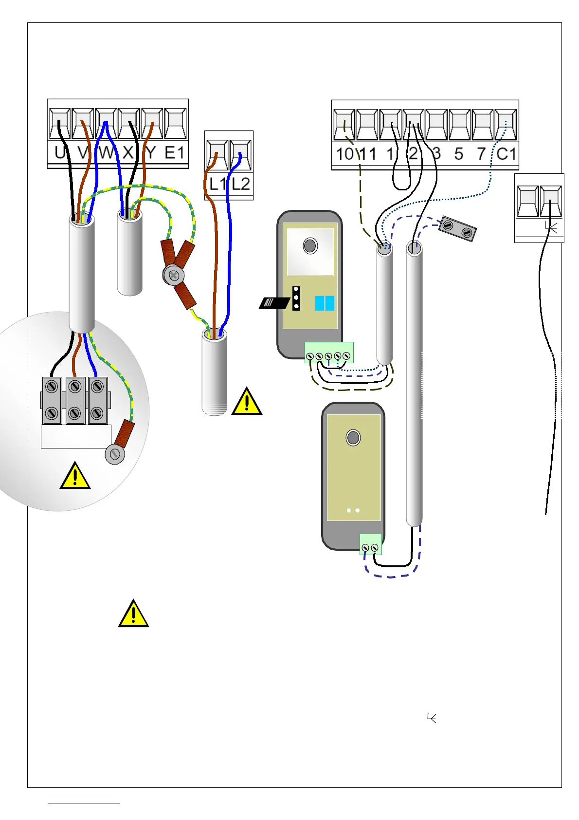
BASIC WIRING
MOTOR CONNECTOR CONTROL CONNECTOR
MAINS
SUPPLY
10 2 TX C NC
DIR
Tx
TX 2
TX
link
MOTORS w3
Frog motors require capacitor in the
control box. M1 capacitor fits to the
black wires, M2 capacitor to the red.
See note r5 for setting Frog direction.
PHOTOCELLS w4
DIR photocells have plug on screw
terminals. The receiver (Rx) needs a
4 core cable. The transmitter needs a
2 core cable. Set the voltage jumper
to 24V. Range is 10m when the Rx &
Tx face each other within 5 degrees.
EARTHING w1
You must create an earthing pointing
in the enclosure to bond the incoming
earth to the two motors and other any
metal gate parts deemed necessary.
MAINS SUPPLY w2
IEEE regulations designated a drive
as a special location which must be
protected by a RCCB. The supply
should be fused at no less than 6A
and supply cable rated appropriately.
Electrical work is notifiable under P
part of building regulations.
.
BOARD SETTINGS w5
Leave switch 1 off. Switch 2 is ‘on’ for
automatic closure. To close the gate
by radio transmitter only, set switch 2
to ‘off’. This disables the auto-close.
RADIO CONTROLS w6
Hang a single core wire 346mm long
from the terminal. If radio range
is poor, a tuned antenna can be fitted.
Plug the radio head onto the plug (9).
See
c1
to set transmitters.
U V W
Motor
1
Earth
point
Cable to
motor 1
W2
Cable to
motor 2
W3
240Vac
supply
W1
Earth
point
Photocell
cable
W6
Photocell
cable
W5
Aerial
cable
346mm
Connec t te rminal :
ZA4 term 10 to DIR-RX term 10
ZA4 term 2 to DIR-RX term 2
ZA4 term C1 to DIR-RX term C
ZA4 term 2 to DIR-TX term 2
DIR-RX term Tx to D IR-RX term Tx

 Loading...