www.came.co.uk Helpline Tel: 0870 012 9000 - 3 -
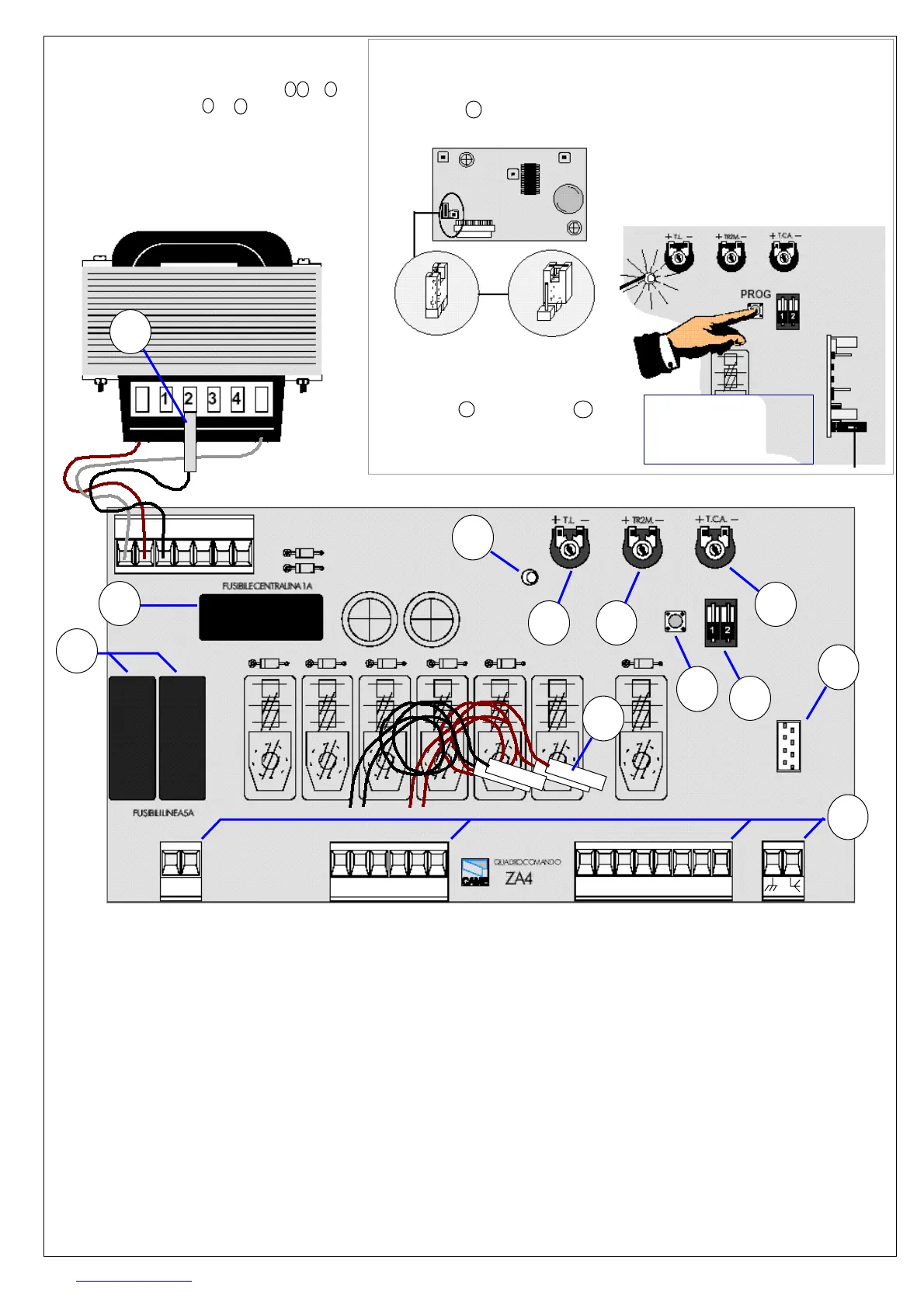
MAIN COMPONENTS
1. Connectors
2. Mains fuses, 5A
3. Accessory fuse, 1.6A
4. Programme button
5. Run time adjustment
6. Interleaf delay
7. Open period
8. Programme DIP’s
9. Radio head plug
10. Indicator LED
11. Torque setting
12.
Capacitor cables
10 11 1 2 3 5 7 C1
U V W X Y E1
1
2
3
7
65
8
9
4
10
L1 L2
12
11
TORQUE SETTING c2
The power of the motor is set on the
transformer. A black wire connects to
the transformer in one of 4 positions
by a white fast-on connector. Select
the lowest setting (
from 1 to 4
) that will
ensure reliable satisfactory operation.
RUN TIME SETTING c3
The motor running time is set by ‘TL’
(
adjustment 5
). Set such that the motor
with the longest travel arrives 2 secs
before the motor switches off. Run
time is less important on motors with
limit switches. The overrun time will
be added to the open period.
INTERLEAF DELAY c4
This allows overlapping gate leaves
to close in the right order by applying
a delay before closing motor 2 (
WXY
)
AUTOMATIC CLOSING c5
Auto-closing is enabled by switching
DIP 2 on (up) on switch block 8. The
gates re-close from 1 to 60 sec after
opening. The open period is set on 7.
The LED indicator flashes once per
second during the open period.
Motor Connector
Control Connector
Mains in Aerial
Changes should be made by competent
persons only. Always disconnect power
before making any wiring changes.
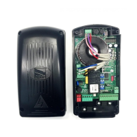
TRANSMITTERS
The TOP432s code is set on switches
inside the transmitter. We recommend
changing the code from that supplied.
To copy a code to a new transmitter,
set the switches until they match.
RADIO CODE SETTING c1
The AF43 radio head plugs onto the
ZA4 board at 9 . Ensure the jumper is
set correctly on both pins. See below:
RECEIVER SETTING
The ZA4 holds the radio code in flash
memory. To set a code, press & hold
prog button 4 . The red LED 10 will
flash. Now press the radio transmitter
button as well. The LED will light con-
stantly until both buttons are released.
COMMISSIONING
The system must be wired fully. Turn 5 6 & 7
fully anticlockwise, then 5 & 7 clockwise by
90
0
. Set the transformer torque to position 1.
Follow commissioning route from c1 to c5. On
FROG systems, read guide T6 for setting the
motor direction.
1- Hold prog button
2- Press transmit
3- Let go both

 Loading...