The data and information reported in this installation manual are susceptible to change at any time and without obligation on CAME cancelli automatici s.p.a. to notify users.
Pag.
1.0 12/2007 © CAME cancelli automatici s.p.a.
ENGLISH
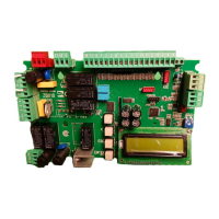
Electrical connections
EN
EN
L-N Power supply 230V (a.c.) 50/60 Hz
U-V-W
230V A.C. gearmotor
+ E D Encoder (E=black, D=red)
F-FA Opening endstop
F-FC Closing endstop
10-11 Terminals for powering 24V (a.c.) accessories
W-E1
Flashing light (socket rating: 230V - 25W max.)
EX-E1
Cycle lamp: (contact rating: 230V – 60W max.)
10-5
Open gate indicator-light (socket rating: 24V - 3W max.)
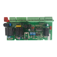
2-CX..CY
Re-open during closing” (N.C.) socket
,
re-close during
opening, partial stop or stand-by Obstacle
2-C7..C8
Re-open during closing” (N.C.) socket
,
re-close during
opening, partial stop or stand-by Obstacle
(
sensitive edges
)
1-2
Stop button (N.C. contact)
2-3
Opening button (N.O. contact)
2-4
Closing button (N.O. contact)
2-3P Partial opening button (N.O.)
2-7
Keyswitch and/or commands button (N.O.)
2-A-B
“NET address” function is set when connecting two paired
operators
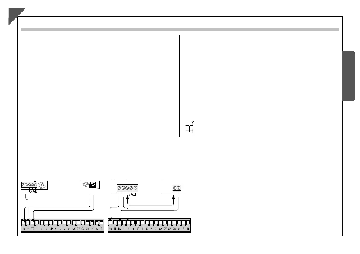
Connection of antenna
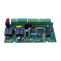
Electrical connection to operate the photocells’ safety test
48
48
48
#
.#
./
.#
#
(DIR)
(DOC)
- The transmitter and receiver, must be connected as shown in
the diagram;
- from the functions menu, select “safety tests” and select
either CX or CY input/s to activate the test.
The data and information reported in this installation manual are susceptible to change at any time and without obligation on CAME cancelli automatici s.p.a. to notify users.
Pag.
1.0 12/2007 © CAME cancelli automatici s.p.a.
ENGLISH
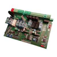
Electrical connections
ENEN
L-N Power supply 230V (a.c.) 50/60 Hz
U-V-W
230V A.C. gearmotor
+ E D Encoder (E=black, D=red)
F-FA Opening endstop
F-FC Closing endstop
10-11 Terminals for powering 24V (a.c.) accessories
W-E1
Flashing light (socket rating: 230V - 25W max.)
EX-E1
Cycle lamp: (contact rating: 230V – 60W max.)
10-5
Open gate indicator-light (socket rating: 24V - 3W max.)
2-CX..CY
Re-open during closing” (N.C.) socket
,
re-close during
opening, partial stop or stand-by Obstacle
2-C7..C8
Re-open during closing” (N.C.) socket
,
re-close during
opening, partial stop or stand-by Obstacle
(
sensitive edges
)
1-2
Stop button (N.C. contact)
2-3
Opening button (N.O. contact)
2-4
Closing button (N.O. contact)
2-3P Partial opening button (N.O.)
2-7
Keyswitch and/or commands button (N.O.)
2-A-B
“NET address” function is set when connecting two paired
operators
Connection of antenna
Electrical connection to operate the photocells’ safety test
48
48
48
#
.#
./
.#
#
(DIR)
(DOC)
- The transmitter and receiver, must be connected as shown in
the diagram;
- from the functions menu, select “safety tests” and select
either CX or CY input/s to activate the test.
 Loading...