The data and information reported in this installation manual are susceptible to change at any time and without obligation on CAME cancelli automatici s.p.a. to notify users.
Pag.
1.0 11/2007 © CAME cancelli automatici s.p.a.
ENGLISH
Electrical lock
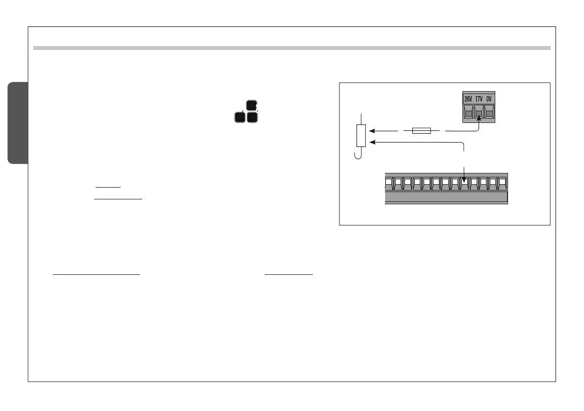
After hooking it up as shown in the illustration, proceed as follows:
a) - Set dip switch 6 to ON (and dip switch 3 to OFF)
E
;
b) - press CH1: the red PROG led will start to blink
B
C
;
c) - when the led stays on (after about 5 seconds) the procedure
is complete;
d) - set to the dip switches back to OFF (or to the previous
position, which depends on the functions selection, see page 12).
N.B.: to return to default (indicator lamp on 10-5), follow the same
procedure while pressing CH2.
ZL90 allows you to connect, alternatively to the indicator light on 10-5, a 12V (15W max) electrolock, and if necessary also the “Ram Blow”
function.
To activate the “ram blow”
(1)
:
dip switches 3 and 6 to ON
dip switches 3 and 6 to ON
) - continue with the above
) - continue with the above
COMMON PROCEDURE.
N.B.: to exclude the ram blow, follow the same procedure while pressing CH2.
(1)
Upon each opening command, the gate leaves press on the closing jamb for one second, assisting the electrolock release operation.
%
0
#8
#9
43
5
place
a 3.15 A
fuse in between
17V
transformer
terminal
The data and information reported in this installation manual are susceptible to change at any time and without obligation on CAME cancelli automatici s.p.a. to notify users.
Pag.
1.0 11/2007 © CAME cancelli automatici s.p.a.
ENGLISH
Electrical lock
After hooking it up as shown in the illustration, proceed as follows:
a) - Set dip switch 6 to ON (and dip switch 3 to OFF)
E
;
b) - press CH1: the red PROG led will start to blink
B
C
;
c) - when the led stays on (after about 5 seconds) the procedure
is complete;
d) - set to the dip switches back to OFF (or to the previous
position, which depends on the functions selection, see page 12).
N.B.: to return to default (indicator lamp on 10-5), follow the same
procedure while pressing CH2.
ZL90 allows you to connect, alternatively to the indicator light on 10-5, a 12V (15W max) electrolock, and if necessary also the “Ram Blow”
function.
To activate the “ram blow”
(1)
:
dip switches 3 and 6 to ON
dip switches 3 and 6 to ON
) - continue with the above
) - continue with the above
COMMON PROCEDURE.
N.B.: to exclude the ram blow, follow the same procedure while pressing CH2.
(1)
Upon each opening command, the gate leaves press on the closing jamb for one second, assisting the electrolock release operation.
%
0
#8
#9
43
5
place
a 3.15 A
fuse in between
17V
transformer
terminal
 Loading...