The data and information reported in this installation manual are susceptible to change at any time and without obligation on CAME cancelli automatici s.p.a. to notify users.
Pag.
1.0 11/2007 © CAME cancelli automatici s.p.a.
ENGLISH
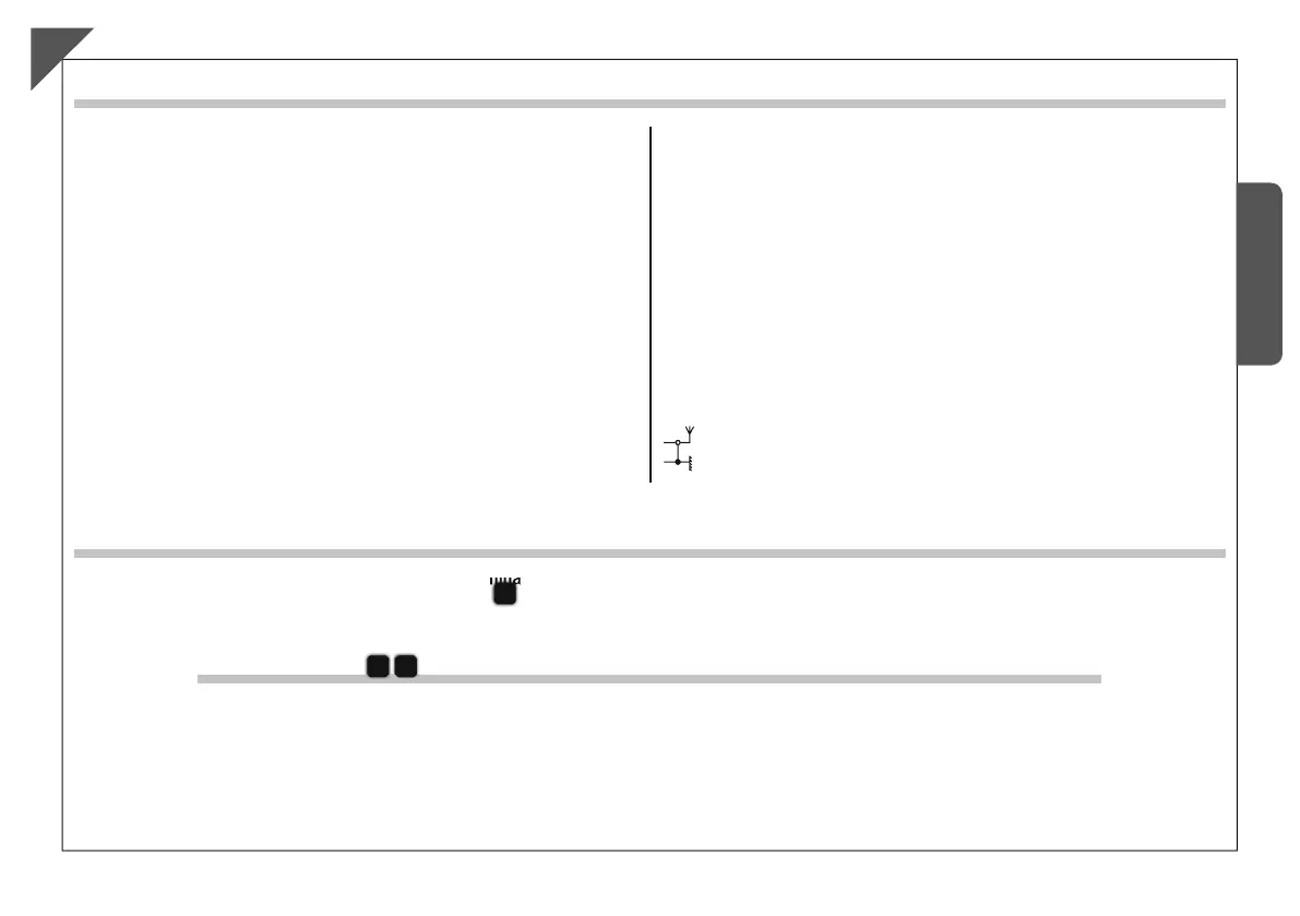
Connection of antenna
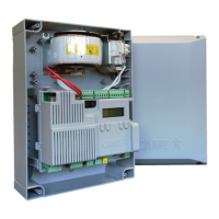
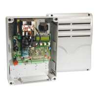
Electrical connections
Power supply 230V (a.c.) 50/60 Hz
Stop button (N.C. socket)
2-CX
2-4
2-3P
2-3
1-2
10-11
B1-B2
Possible output of the radio receiver’s second channel
(N.O.). Socket rating: 5A-24V (d.c.).
L-N
Terminals for powering 24V (a.c.) accessories
M1-N1-ENC1
24V d.c. gearmotor featuring delayed action on
opening
M2-N2-ENC2
24V d.c. gearmotor featuring delayed action on
closing
10-E1
Flashing light (socket rating: 24V - 25W max.)
Open gate indicator-light (socket rating: 24V - 3W max.).
10-5
2-CY
-“partial stop”/“Stand-by Obstacle” (N.C.) socket
(see Function Selection, page 11)
“Re-open during closing” (N.C.) socket
Keyswitch and/or opening button (N.O.)
Keyswitch and/or partial opening button (N.O.)
Keyswitch and/or closing button (N.O.)
2-7
Keyswitch and/or commands button (N.O.)
EN
-Connect the antenna’s RG58 cable to the apposite terminals.
-Lock the radiofrequency card into the electronic card
D
AFTER CUTTING OFF THE POWER SUPPLY (or after disconnecting the batteries).
N.B.: the electronic card only recognises the radiofrequency card when the power is on.
Activating the remote control
Memorisation
B
C
CH1 = Channel for direct command to a function of the the gearmotor’s card,
(“open only / “open-close-invert” or “open-stop-close-stop” command,
depending on the choice made on DIP switches 2 and 3).
CH2 = Channel for direct command an accessory device connected to
B1-B2.
-Keep the “CH1” button on the electronic card pressed. The LED fl ashes.
-Press the transmitter button you wish to memorise. The LED will stay on to show memorisation has been successful.
-Repeat the points 1 and 2 procedures for the “CH2” button associating this to another button on the transmitter
.
The data and information reported in this installation manual are susceptible to change at any time and without obligation on CAME cancelli automatici s.p.a. to notify users.
Pag.
1.0 11/2007 © CAME cancelli automatici s.p.a.
ENGLISH
Connection of antenna
Electrical connections
Power supply 230V (a.c.) 50/60 Hz
Stop button (N.C. socket)
2-CX
2-4
2-3P
2-3
1-2
10-11
B1-B2
Possible output of the radio receiver’s second channel
(N.O.). Socket rating: 5A-24V (d.c.).
L-N
Terminals for powering 24V (a.c.) accessories
M1-N1-ENC1
24V d.c. gearmotor featuring delayed action on
opening
M2-N2-ENC2
24V d.c. gearmotor featuring delayed action on
closing
10-E1
Flashing light (socket rating: 24V - 25W max.)
Open gate indicator-light (socket rating: 24V - 3W max.).
10-5
2-CY
-“partial stop”/“Stand-by Obstacle” (N.C.) socket
(see Function Selection, page 11)
“Re-open during closing” (N.C.) socket
Keyswitch and/or opening button (N.O.)
Keyswitch and/or partial opening button (N.O.)
Keyswitch and/or closing button (N.O.)
2-7
Keyswitch and/or commands button (N.O.)
EN
-Connect the antenna’s RG58 cable to the apposite terminals.
-Lock the radiofrequency card into the electronic card
D
AFTER CUTTING OFF THE POWER SUPPLY (or after disconnecting the batteries).
N.B.: the electronic card only recognises the radiofrequency card when the power is on.
Activating the remote control
Memorisation
B
C
CH1 = Channel for direct command to a function of the the gearmotor’s card,
(“open only / “open-close-invert” or “open-stop-close-stop” command,
depending on the choice made on DIP switches 2 and 3).
CH2 = Channel for direct command an accessory device connected to
B1-B2.
-Keep the “CH1” button on the electronic card pressed. The LED fl ashes.
-Press the transmitter button you wish to memorise. The LED will stay on to show memorisation has been successful.
-Repeat the points 1 and 2 procedures for the “CH2” button associating this to another button on the transmitter
.

 Loading...