BARTON
®
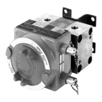
MODEL 752 & 752A
DIFFERENTIAL PRESSURE
TRANSMITTERS
For Nuclear Service
User Manual
Part No. 9A-C10820, Rev. 02
November 2015
Contents
Safety ............................................................................................................ 2
Section 1—Introduction ................................................................................. 3
General ......................................................................................................... 3
Product Description....................................................................................... 3
Differential Pressure Unit ......................................................................... 3
Electronic Transmitter................................................................................ 4
Power Supply ............................................................................................ 4
Zero and Span Control.................................................................................. 4
Zero Control .............................................................................................. 4
Span Control ............................................................................................. 5
Specications ............................................................................................... 5
Qualication............................................................................................... 7
Section 2—Theory of Operation .................................................................... 9
Basic Components ........................................................................................ 9
Differential Pressure Unit (DPU) ............................................................... 9
Electronic Transmitter...............................................................................11
Basic Operation ...........................................................................................11
Surge Voltage Protection Circuit .............................................................11
Reverse Polarity Protection ......................................................................11
Regulator ..................................................................................................11
Strain Gage Bridge Network ................................................................... 12
Signal Amplier........................................................................................ 12
Current Amplier...................................................................................... 12
Temperature Compensation........................................................................ 12
Section 3—Installation, Startup, and Shutdown ........................................ 13
Overview ..................................................................................................... 13
Unpacking/Inspection.................................................................................. 13
Initial Calibration Check .............................................................................. 13
Mounting ..................................................................................................... 13
Wall or Rack Mounting ............................................................................ 13
Piping Guidelines ........................................................................................ 14
Electrical Connections ............................................................................... 14
Loop Resistance Calculations ................................................................. 16
Maximum Loop Resistance ..................................................................... 17
EMI/RFI Shielding ....................................................................................... 17