ENGINEERED & PROCESS VALVES
02/2011 / IOM-WKM-GATE-PRS-01
5
Installation, Operation and Maintenance Manual
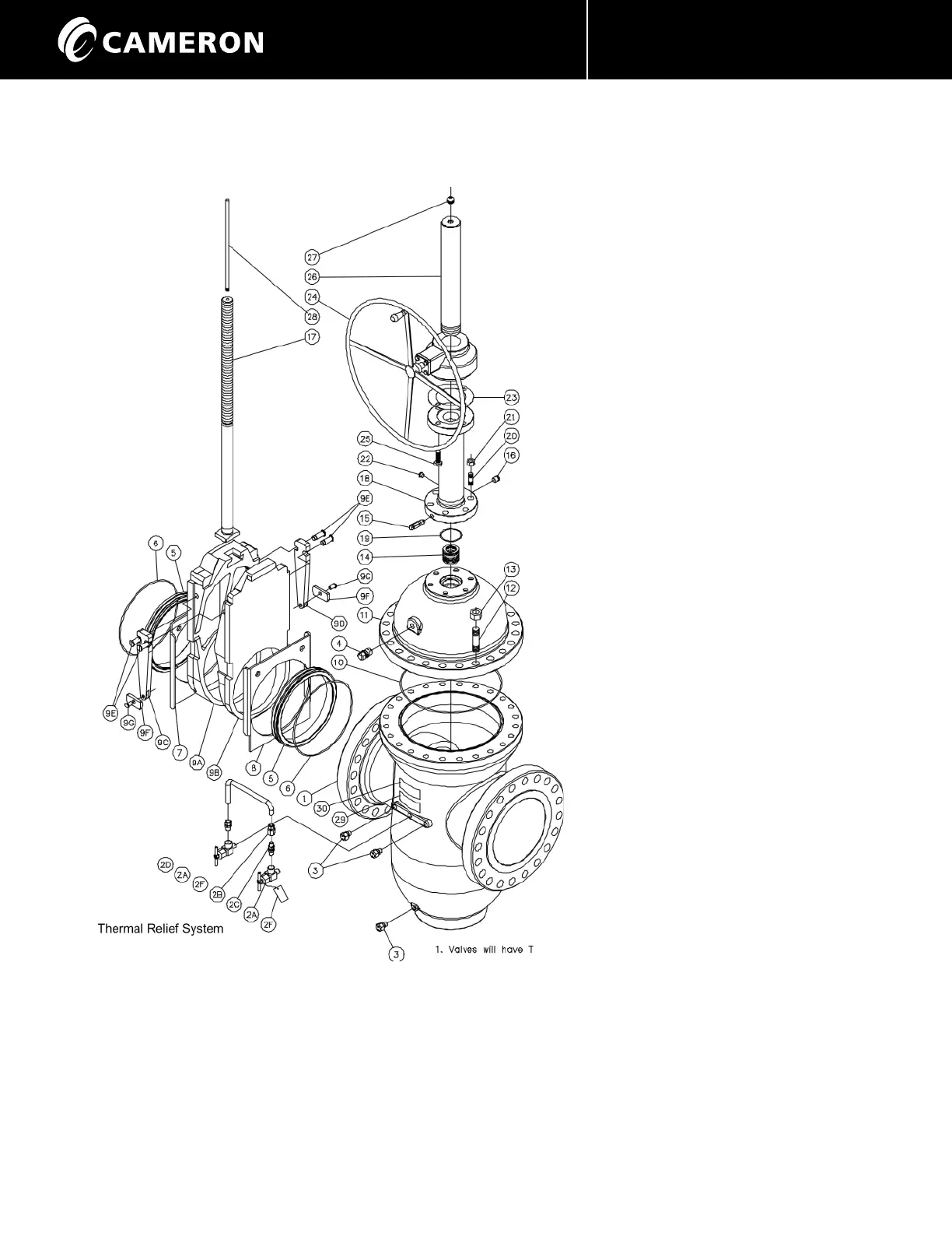
BILL OF MATERIALS (6” - 12” 1500, 14” - 36” 300 - 900)
MODEL “E” & “E1C”
ITEM DESCRIPTION
1. Body
2. Thermal Relief Valve System
2A. Needle Valves
2B. Female Connector
2C. Check Valve
2D. Male Connector
2E. Tubing
2F. Needle Valve Caution Tag
3. Drain and Seat Lube Fittings
4. Vent Fittings
5. Seats
6. Seat O-Rings
7. Gate Seat Skirt
8. Segment Seat Skirt
9. Gate and Segment Assembly
9A. Gate
9B. Segment
9C. Lever Lock Arm #1
9D. Lever Lock Arm #2
9E. Lever Lock Arm Pins
9F. Lever Lock Shoe
9G. Shoe Pins
10. Bonnet Seal
11. Bonnet
12. Studs
13. Nuts
14. Packing Set
15. Packing Fitting Assembly
16. Packing Plug
17. Stem
18. Yoke Tube
19. Yoke Tube Seal
20. Studs
21. Nuts
22. Pull Plug
23. Gasket
24. Bevel Gear Operator
25. Hex Head Bolts
26. Stem Protector
27. Rod Wiper
28. Indicator Rod
29. Caution Tag for Trapped
Pressure
30. Nameplate
Figure 3 - WKM Pow-R-Seal Gate Valve 6”- 12” ASME Class 1500,
14” - 36” 300 - 900.
Note: On Model “E1C” the Packing Set is located in the Bonnet
and therefore the Packing Injection Port is on the small O.D. at
the top of the Bonnet.
 Loading...