21
Appendix C. Serial Port Pin Outs
C.1 RS-232 Communications Port
C.1.1 Pin-Out
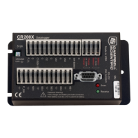
Pin configuration for the CR200(X) RS-232 9-pin port is listed in TABLE.
CR200(X) RS-232 Pin-Out p. 21.
The C
R200(X) RS-232 port is a DCE (Data Communication Equipment) device.
A limited version of the RS-232 port is supported with no hardware flow
control. The most common use of the Datalogger's RS-232 port is a connection
to a computer DTE device. A standard DB9-to-DB9 cable can connect the
computer DTE device to the Datalogger DCE device.
The CR200(X) RS-232 port is not electrically isolated. Connection to an AC
powered computer may cause ground loops leading to measurement problems.
Maximum input = ±25 V
Maximum Output = ±13 V
Typical Output = ±5.4 V
The following table describes the Datalogger's RS-232 pin function with
standard DCE naming notation.
Table 28. CR200(X) RS-232 Pin-Out
PIN: Pin number
O: Signal Out of the CR200(X) to a RS-232 device
I: Signal Into the CR200(X) from a RS-232 device
PIN DCE Function Logger Function I/O Description
1
N/A
Not Connected
2 TX TXD O Asynchronous data Transmit
3 RX RXD I Asynchronous data Receive
4
N/A
Not Connected
5 GND GND
Ground
6 DSR DTR O Data Terminal Ready
7
N/A
Not Connected
8 CTS RTS O Request to send
9
N/A
Not Connected

 Loading...