TDR100
)
L
L
w
v
=
⋅+
+
−
θ
max
.
.
0176
0114
2
with L the actual probe rod length, and, θ
v-max
the maximum expected
volumetric water content. Two m is added for the .5 m before the probe and
some distance after the probe end. For example, using a CS610 with 0.3 m
probe rod length in a soil with a porosity of 0.6 gives an estimated apparent
probe length of 4.04 m. Setting the Waveform Length to 4 m is recommended.
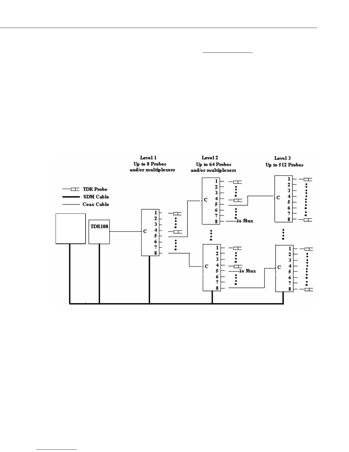
5. System Components: Datalogger Control
5.1 General
Datalogger
FIGURE 5-1. TDR System Components
5.2 Datalogger
Campbell Scientific CR800, CR850, CR1000, and CR3000 dataloggers use
Instruction “TDR100” to control the TDR100 measurement sequence and store
the resulting data. PC400 or LoggerNet (version 3.0 or higher) are used to
create and send the CRBasic Program to the datalogger.
Campbell Scientific CR10X and CR23X dataloggers use Instruction 119 and
various other instructions to control the TDR100 measurement sequence and
store the resulting data. PC208W (version 3.1 or higher) or LoggerNet are
used to link the datalogger to a computer for data and program transfer.
11

 Loading...

