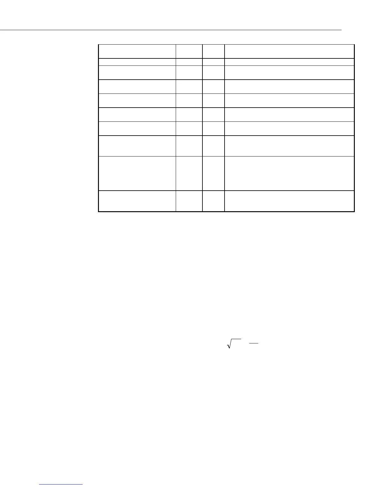
TDR100
Waveform Averaging 4: FP 1 -
128
Number of reflections averaged by the TDR100.
V
p
5: FP .1 - 1 relative propagation velocity
Points 6: FP 20-
2048
number of points in waveform
Cable length (meters) 7: FP 0 -
2100
distance for TDR100 corresponding with
beginning of waveform
Window Length
(meters) 8:
FP .1 -
700
length of reflection waveform
Probe length 9: 4 Physical length of the exposed portion of the
metal rods
Probe offset 10: FP 0 -
1.0
Accounts for portion of rods not exposed to soil.
See Section 6.2.10.
Input location 11: 4 Input storage location for measurement result. If
waveforms are chosen for output, this location is
occupied by the first data point.
Multiplier 12: FP Multiplication factor applied to La/L and stored
in input location specified in parameter 11.
Set to 1 when parameter 2 is 1 or 2.
For electrical conductivity, can be used for probe
constant value.
Offset 13: FP Offset value added to La/L and stored in input
location specified in parameter 11. Set to 0 when
parameter 2 is 1 or 2.
6.3 Discussion of TDR Instruction Parameters (Instruction 119)
6.3.1 Parameter 1: SDM Address
The SDM address of the TDR100 is set by selecting hexadecimal values with
the thumbwheel switch on the TDR100 front panel. Instruction 119 requires a
2 digit integer that is the base 4 value of the TDR100 address. See Table 5-1
6.3.2 Parameter 2: Output Option
6.3.2.1 Enter 0: Measure La/L
In the section on TDR Principles, the equation
K
L
L
a
a
=
is presented. The terms of this equality can be related to volumetric water
content using empirical relationships such as equations [3] and [4] shown in
Section 7. The apparent length of the probe rods, L
a
, changes with water
content. Dividing L
a
by the real rod length, L, gives the square root of
dielectric constant. The L
a
/L value is empirically related to volumetric water
content using calibration functions of the form θ
v
= f(L
a
/L). See Section 7 for
commonly used calibration functions.
21

 Loading...

