TDR100
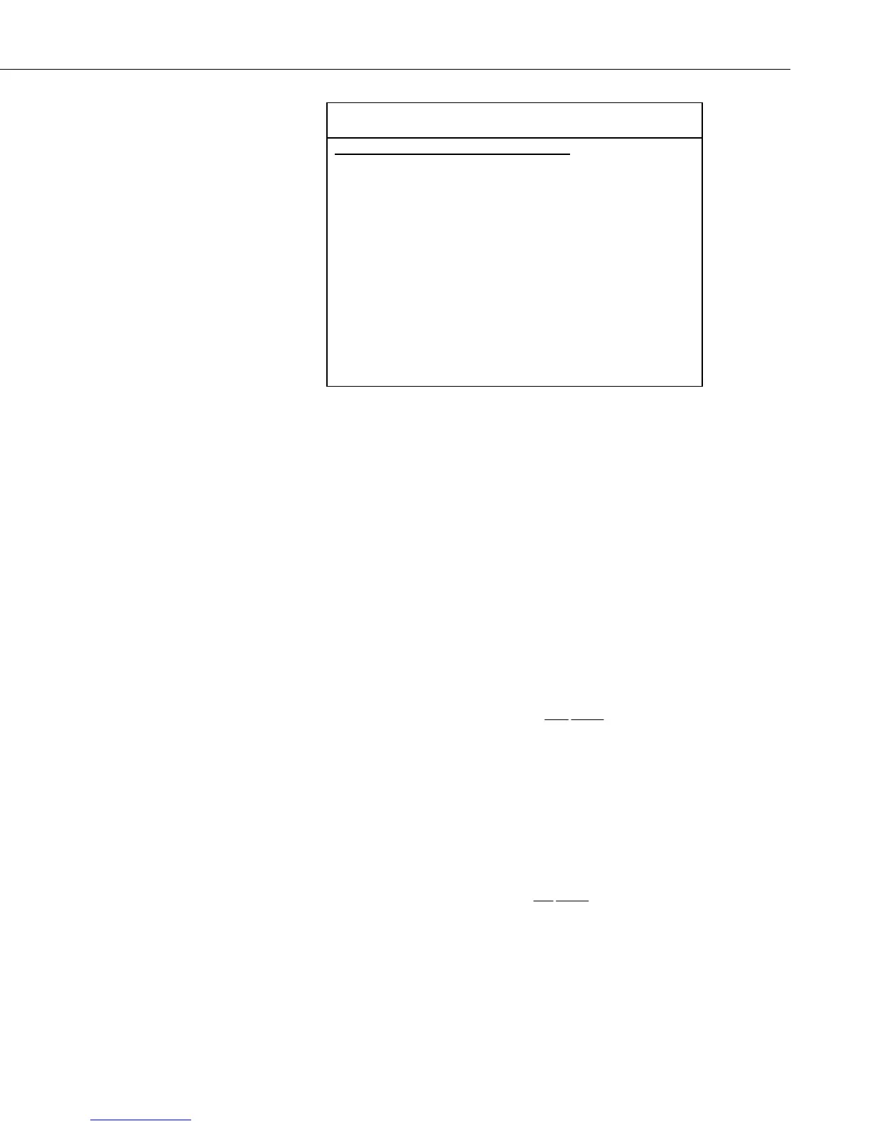
TABLE 6-1. Reflection waveform array header elements.
Description of Array Header Elements
1 averaging
2 propagation velocity
3 number of data points
4 cable length
5 window length
6 probe rod length
7 probe offset
8 multiplier
9 offset
6.3.12 Parameter 12: Multiplier
Multiplication factor applied to the value stored in the input location specified
in parameter 11. Set to 1 when parameter 2 is 1 or 2. The multiplier can be
used for the probe constant value when measuring electrical conductivity.
6.3.13 Parameter 13: Offset
Offset value added to the value stored in input location specified in parameter
11. Set to 0 when parameter 2 is 1 or 2.
6.3.13.1 Probe Constant for Electrical Conductivity Measurement
The section, TDR Principles, presents the equation used for soil bulk electrical
conductivity. For convenience, it is repeated here.
σ
ρ
ρ
=
−
+
Z
c
1
p
1
A portion of the datalogger algorithm evaluates the reflected waveform to
determine the applied and reflected voltages. From this, the reflection
coefficient, ρ, can be calculated. The term, Z
c
, is the reflectometer impedance
and is a constant 50 ohms.
The electrical conductivity routine in the datalogger returns the value
11
1Z
c
+ ρ
which must be multiplied by the probe constant, K
p
, to get an electrical
conductivity value.
25

 Loading...

