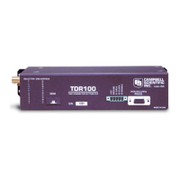
TDR100
FIGURE 10-1. Twenty-nine CS605 or CS610 probes connected to 4ea SDMX50 multiplexers.
Example 5, Trouble Shooting Program for SDMX50 Multiplexer, Datalogger
Control Ports, and Analog Measurements
The following program can be used to test the operation of the SDMX50
Multiplexer and the datalogger control ports.
;{CR10X}
;Program Name: Example 5
*Table 1 Program
01: 5 Execution Interval (seconds)
;The Following Instruction 20 configures all 8 Control Ports as Outputs.
;This allows the user to manually set the ports high (+5V) or low (0V) in order
;to check the port operation with a volt meter. Ports and flags can be set with
;the Keyboard Display (*6 Mode, Datalogger Manual Section 1.3) or from the Connect
;Screen of PC208W or LoggerNet.
1: Set Port(s) (P20)
1: 7777 C8..C5 = output/output/output/output
2: 7777 C4..C1 = output/output/output/output
;To test wiring and multiplexer operation, the user can set Flag 1 and
;Instruction 109 will switch the SDMX50 multiplexer(s) to channel 8.
;(Starting at channel 1 each time P109 is executed.)
;If Flag 1 is LOW Instruction 109 will NOT be executed. The default
;status for User Flags 1-8 is low.
50

 Loading...