EasyManua.ls Logo

Camus Hydronics DFH/W2000 - Page 12

Camus Hydronics DFH/W2000
90 pages
Print Icon
To Next Page IconTo Next Page
To Previous Page IconTo Previous Page
Loading...
7
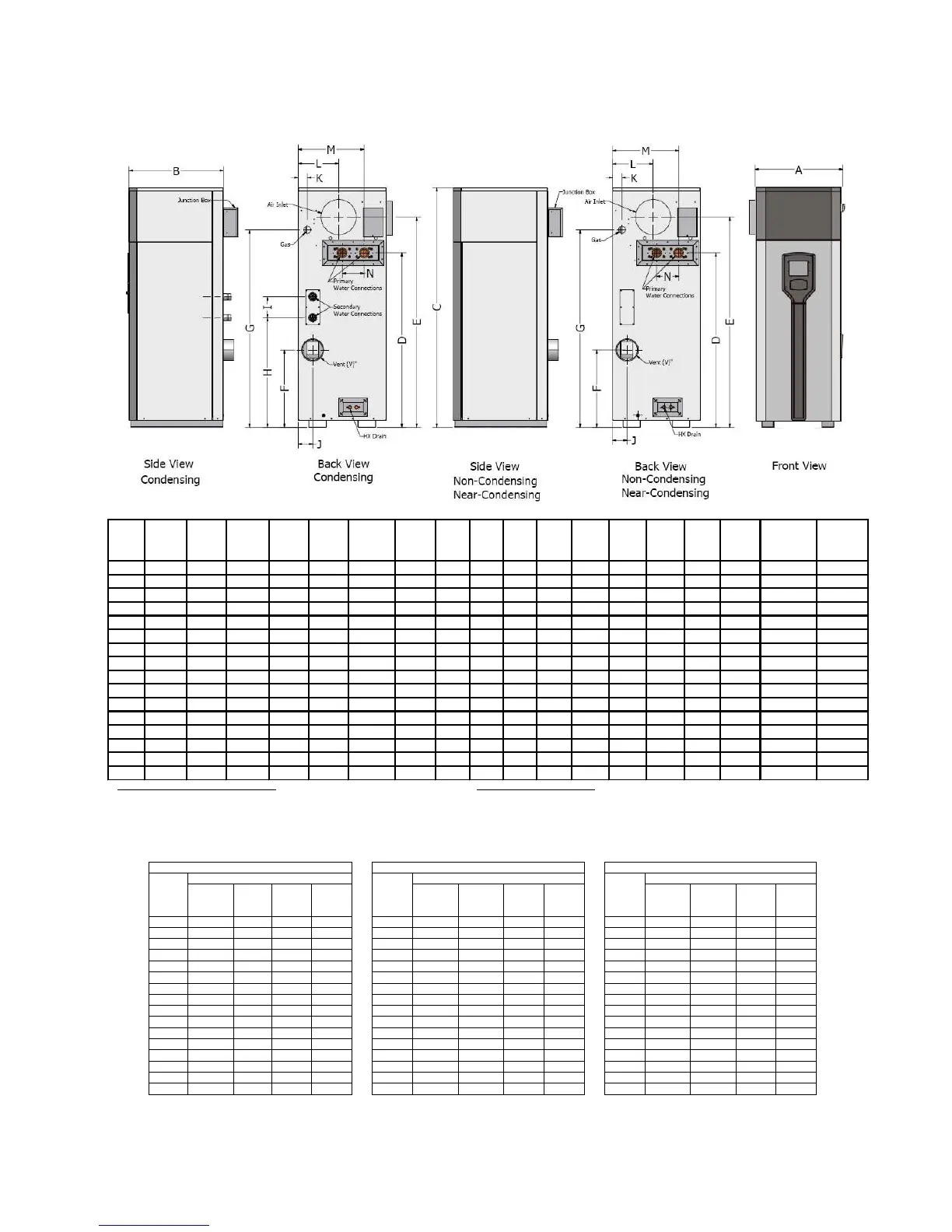
Table 3: Appliance Dimensions and Specifications [in.]
Model Width "A" Depth "B" Height "C"
Water
Conn. "D"
Air Inlet
"E"
Flue Height
"F"
Gas
Height
"G"
"H" "I" "J" "K" "L" "M" "N"
Air Inlet
Dia. "W"
Water
Conn.
Prim.
Water Conn.
Sec. Grooved
(Optional)
Gas Conn.
[NPT]
500
25
27
45 5/8
27
37 1/4
13 1/4
33 5/8
17 3/4
6
4 1/8
2 5/8
11 1/2
18 3/4
6 1/4
6
2
1 1/2
1
750
25
27
55
36 3/8
46 5/8
15 3/4
43
25
6
4 1/8
2 5/8
11 1/2
18 3/4
6 1/4
8
2
1 1/2
1
1100
25
27
68 1/4
49 5/8
59 7/8
22
56 1/4
31 1/8
6
4 1/8
2 5/8
11 1/2
18 3/4
6 1/4
8
2
1 1/2
1
1200
25
27
68 1/4
49 5/8
59 7/8
22
56 1/4
31 1/8
6
4 1/8
2 5/8
11 1/2
18 3/4
6 1/4
8
2
1 1/2
1
1500
29 3/8
31 3/4
58 1/8
38 1/4
48 5/8
16 3/8
45 7/8
24 1/2
6
3 7/8
1 7/8
13 1/2
22 3/8
10 1/4
10
2 1/2
1 1/2
1 1/4
1750
29 3/8
31 3/4
62 5/8
42 5/8
53 1/8
16 3/8
50 3/8
24 1/2
6
3 7/8
1 7/8
13 1/2
22 3/8
10 1/4
10
2 1/2
1 1/2
1 1/4
2000
29 3/8
31 3/4
66 7/8
46 7/8
57 3/8
20
53 5/8
28 3/4
6
3 7/8
1 7/8
13 1/2
22 3/8
10 1/4
12
3
1 1/2
1 1/4
2500
29 3/8
31 3/4
73 1/2
52 5/8
63 5/8
25
3/4
60 3/8
34 1/2
6
3 7/8
1 7/8
13 1/2
22 3/8
10 1/4
12
3
1 1/2
1 1/2
3000
29 3/8
31 3/4
79 1/2
58 5/8
69 5/8
31 3/4
66 3/8
40 1/2
6
3 7/8
1 7/8
13 1/2
22 3/8
10 1/4
12
3
1 1/2
1 1/2
3500
29 3/8
31 3/4
86 1/2
63 5/8
76
24 7/8
72 5/8
32 7/8
20
3 7/8
1 7/8
13 1/2
22 3/8
10 1/4
14
4
1 1/2
2
4000
29 3/8
31 3/4
91 1/2
68 5/8
81
29 7/8
77 5/8
32 7/8
20
3 7/8
1 7/8
13 1/2
22 3/8
10 1/4
14
4
1 1/2
2
4500
29 3/8
31 3/4
96 1/2
73 5/8
86
34 7/8
82 5/8
42 7/8
20
3 7/8
1 7/8
13 1/2
22 3/8
10 1/4
14
4
1 1/2
2 1/2
5000
29 3/8
31 3/4
101 1/2
78 5/8
91
39 7/8
87 5/8
47 7/8
20
3 7/8
1 7/8
13 1/2
22 3/8
10 1/4
14
4
1 1/2
2 1/2
4504
35 3/4
39 1/4
83
59 3/4
72 1/4
20 3/4
67 7/8
28 7/8
20
2 1/2
3 1/2
17 7/8
25 5/8
12
14
4
1 1/2
2 1/2
5004
35 3/4
39 1/4
88 1/4
65
77 1/2
26
72 1/4
34 1/8
20
2 1/2
3 1/2
17 7/8
25 5/8
12
14
4
1 1/2
2 1/2
6004
35 3/4
39 1/4
102
75 1/2
91
35 1/2
85 1/2
44 5/8
20
2 1/2
2 3/4
17 7/8
25 5/8
12
14
4
1 1/2
3
Copper and copper nickel heat exchanger Stainless steel heat exchanger:
500 – 1200 appliance inlet/outlet connections are 2” NPT 500 – 1200 appliance inlet/outlet connections are 2” groove lock
1500 – 5000 appliance inlet/outlet connections are 3” NPT 1500 – 2500 appliance inlet/outlet connections are 2-1/2” groove lock
3000 - 5000 appliance inlet/outlet connections are 3” groove lock
4504 - 6004 appliance inlet/outlet connections are 4” groove lock
Table 4: Vent Sizes for a Single Appliance
DynaFlame®
Non
-
Condensing
DynaFlame®
Near
-
Condensing
(DFX)
DynaFlame®
Condensing
Model
Vent Diameter Inches
Model
Vent Diameter Inches
Model
Vent Diameter Inches
Outdoor
Cat III
Up to
50 ft
Cat III
Up to
100 ft
Cat I Outdoor
Cat IV
Up to
50 ft
Cat IV
Up to
100 ft
Cat II
Outdoor
Cat IV
Up to
50 ft
Cat IV
Up to
100 ft
Cat II
0500 4 4 6 8
0501 4 4 6 5
0502 4 4 6 5
0750 6 6 8 10 0751 6 6 8 6 0752 6 6 8 6
1100
6
6
8
10
1101
6
6
8
7
1102
6
6
8
7
1200 6 6 8 10 1201 6 6 8 7 1202 6 6 8 7
1500 7 7 10 12
1501 7 7 10 8
1502 7 7 10 8
1750 7 7 10 12 1751 7 7 10 8 1752 7 7 10 8
2000
8
8
12
14
2001
8
8
12
9
2002
8
8
12
9
2500 8 8 12 14 2501 8 8 12 9 2502 8 8 12 9
3000 8 8 12 14
3001 8 8 12 10
3002 8 8 12 10
3500
9
9
14
16
3501
9
9
14
12
3502
9
9
14
12
4000 9 9 14 16 4001 9 9 14 12 4002 9 9 14 12
*4500 10 10 14 16 *4501 10 10 14 12 *4502 10 10 14 12
4504 10 10 14 16
4514 10 10 14 12
4524 10 10 14 12
*5000
10
10
14
16
*5001
10
10
14
12
*5002
10
10
14
12
5004 10 10 14 16 5014 10 10 14 12 5024 10 10 14 12
6004 12 12 14 16 6014 12 12 14 12 6024 12 12 14 12

Table of Contents

Related product manuals