3.2 GAS PIPING
All gas connections must be made with pipe joint compound
resistant to the action of liquefied petroleum and natural gas.
All piping must comply with local codes and ordinances.
3.3 INSTALL PIPING
• The gas line should be sufficient to handle the total
installed capacity. Verify pipe size with gas supplier.
• Use new, properly threaded black iron pipe free from
burrs. Avoid flexible gas connections. Internal diameter of
flexible gas lines may not provide appliance with proper
volume of gas.
• Install a manual main gas shutoff valve at the appliance
gas inlet, outside of the appliance and before the gas
valve. Install a joint union at the appliance gas line
connection for ease of service and removal of the gas
train.
• Run pipe to the Appliance gas inlet.
• Install a sediment trap in the supply line to the Appliance
gas inlet.
• Apply a moderate amount of good quality pipe compound.
• For LP gas, consult your LP gas supplier for expert
installation.
The appliance and its individual gas shut-off valve must be
disconnected from the supply piping when pressure testing the
gas supply piping at pressures above ½ PSI
Table 7: Gas Pressures at Inlet to Appliance
11 14
* 3” for 500 and 750 models. 3.5” for 1100 and 1200 models.
4.5” for models 1500 – 6000. Recommended regulator
settings is 7.0” w.c
The gas supply line must be of adequate size to prevent undue
pressure drop and must never be smaller than the size of the
connection on the appliance. Sizing based on Table 7 is
recommended.
Before operating the appliance, the complete gas train and
all connections must be tested using soap solution.
Verify that the appliance is supplied with the type gas
specified on the rating plate. Heating values of local
natural gas are to be between 950 and 1010 Btu/ft
3
.
Consult factory if heating values are outside this range or
if a gas with a mixture of constituents is being used.
3.4 AIR/GAS RATIO VALVE
The main gas valves supplying gas to the burner for
models 2000 to 5000 on this appliance utilize a servo
pressure regulator providing a slow opening, fast closing
safety shut off and an air/gas ratio control valve for the gas
combustion process. This gas valve controls the pressure
difference across the flow orifice in the manifold supply
line as a function of the pressure difference across the
combustion air supply to the burner. The actuator
maintains a constant air to gas ratio as the volume of air
changes based on the operation of the combustion air fan.
The valve is a 1:1 differential pressure air/gas ratio
controller. The valve generates the same pressure
difference on the gas side as it senses on the air side.
Models 500 to 1750 utilize a 1:1 ratio dual seat negative
pressure gas valve. Models 2000 – 3000 utilize a 1:1
air/gas ratio control valve and a safety solenoid valve.
Models 3500 – 6000 utilize a 1:1 air/gas ratio control and
regulating gas valve. The regulating gas valve performs
the functions of a pressure regulator, safety shutoff. Full
closing of the valve seat occurs in less than 0.8 seconds
when the valve is de-energized. Operation of the gas
valve in combination with the combustion air fan allows the
burner input rate to vary from 20% to 100% based on
temperature demand. The inlet gas supply pressure must
be maintained within the specified minimum and maximum
pressures.
The air/gas ratio is preset at the factory and adjustment is
not usually required if gas supply pressure is maintained
within the specified range.
There are no serviceable parts on the dual seat negative
pressure air/gas ratio valve control.
A reduction of up to 30% is permitted in the inlet gas
pressure between light off and full fire conditions.
If the manifold differential pressure is to be measured,
refer to section 3.8 Checking Differential Air and Gas
Pressures for proper measurement.
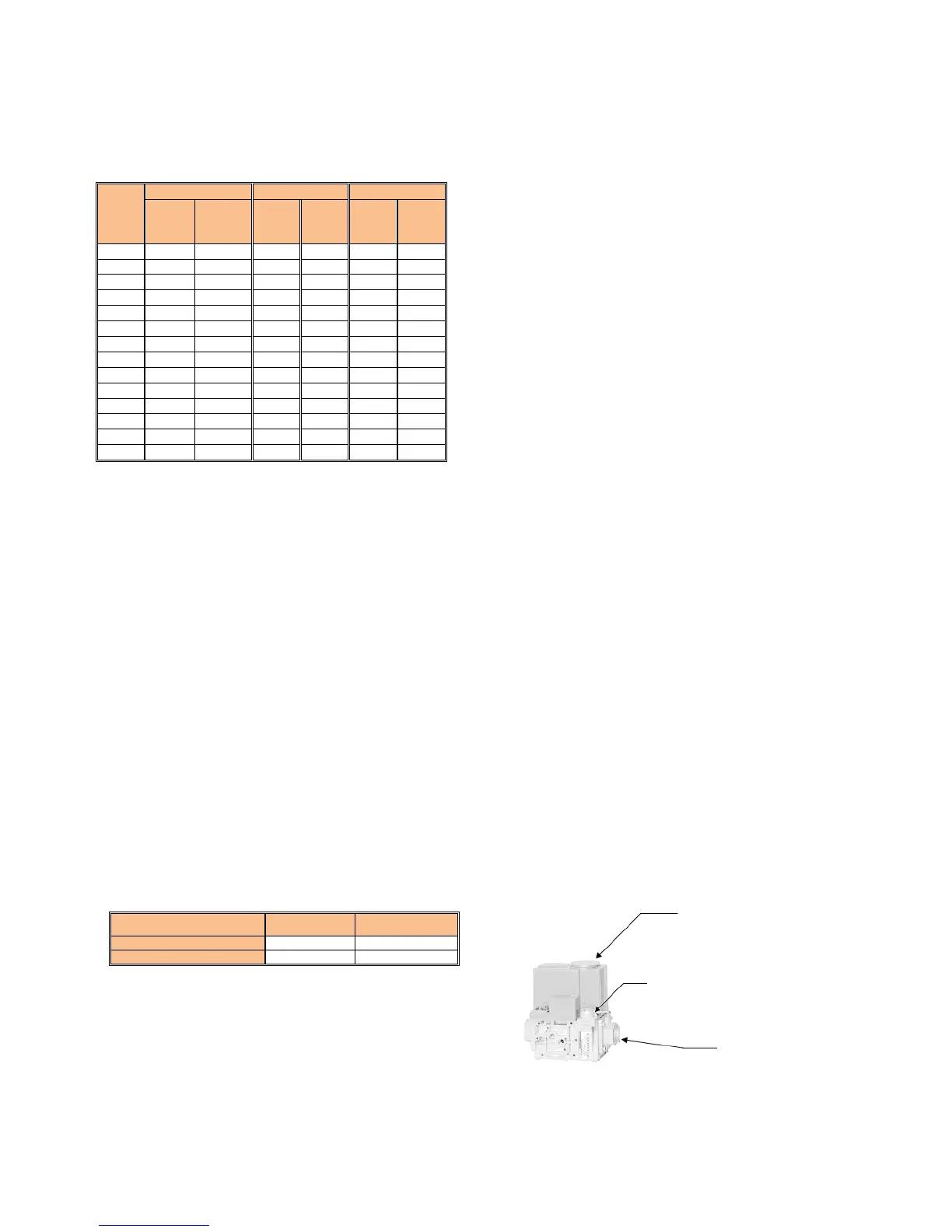
Figure 8: DF500 – 1750 1:1 Negative Pressure Air Gas
Ratio Control Valve
Lift top cover to access high fire
air/gas ratio adjustment
(use 3mm allen key for adjustment,
counter-clockwise increases CO
2
)
Low fire air/gas ratio adjustment
(use T-40 for adjustment,
clockwise increases CO
2
)
Gas Inlet