407.4 24.5
4.8 CONDENSER HEAT RECOVERY
MODULE (CHRM)
The DynaFlame® ALL Stainless Steel CHRM is mounted
in a stainless steel inner jacket chamber at the right side of
the appliance facing the appliance. The CHRM is
constructed from all stainless steel headers and special
multiple horizontal stainless tubes. This CHRM is
designed to maximize heat transfer efficiency by fully
condensing flue products and is suitable to resist the low
PH of condensate.
The CHRM must be supplied with adequate water flow at
all times during operation. Do not operate the appliance
with the CHRM piped out or isolated.
The CHRM is mounted in the discharge of the flue
products from the primary heat exchanger. This allows
additional heat to be absorbed from the flue products
exhausted from the combustion process. If isolation valves
are provided on the CHRM, the provision of a relief valve
at the outlet of the CHRM is recommended. This valve is
to be sized at minimum for 10% of the input of the
appliance and is to be piped to drain.
When cold water supply with temperatures less than 130
ºF (54 ºC) passes through the CHRM it will cool the flue
products below dew points resulting in the formation of
condensation. Furthermore, the volumetric flow rate of the
flue gases will be reduced. Never supply water at less
than 35
o
F to the CHRM.
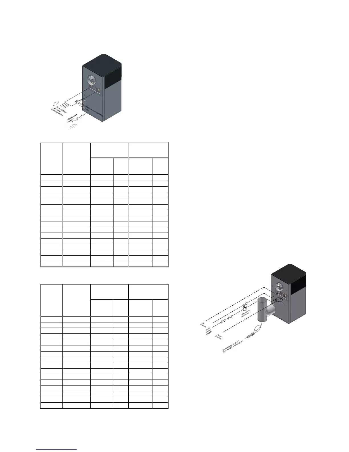
The appliance CHRM loop may be used in condensing
mode for a variety of application including domestic hot
water and hydronic space heating. Recommended piping
arrangement is shown in Figure 18 Maximum
recommended flows through the CHRM is summarized in
Table 10.
Figure 19: Typical Condensing System
Condensate from the DynaFlame® must be treated before
being discharged to drain. PH level of the condensate is to
be checked regularly and the neutralizing medium is to be
replaced as required. A neutralizing cartridge is available
from the factory. The condensing DynaFlame® must be
vented using only special venting type AL29-4C stainless
steel or equivalent, please follow instructions detailed
below.