Figure 17: Chilled Water System
4.3 INLET AND OUTLET CONNECTIONS
• All water connections are groove-lock fittings.
• For ease of service, install unions on inlet and outlet of the
appliance. The connection to the appliance marked “Inlet”
on the header should be used for return from the system.
The connection on the header marked “Outlet” is to be
connected to the supply side of the system.
4.4 MINIMUM PIPE SIZE REQUIREMENTS
The equivalent number of straight feet of pipe for each valve
and fitting in the connecting piping must be considered to
properly arrive at the total equivalent feet of straight pipe in the
field installed piping to the appliance. See the piping
requirements in Part 11 - Installation section of this manual.
Consult factory if longer piping distances are required for a
specific application.
4.5 HEAT EXCHANGER
This appliance uses stainless steel fin tubing to maximize the
heat transfer process. The heat exchanger is comprised of
vertical tubes welded directly into two circular stainless steel
headers. This heat exchanger is designed to withstand 160
PSIG working pressure. A series of “V” shaped baffles are
installed between the individual tubes to control the movement
of the flue products over the finned tubes to maximize
efficiencies. When servicing, take special care to ensure that
baffles are properly located and maintained in factory
condition. Replace any damaged baffles including factory
supplied ceramic facing tape.
A factory recommended circulating pump ensures proper water
flow during burner operation and creates enough water
turbulence inside the stainless steel tubes and header that
prevents the formation of sediments. Temperature rise and
scale formation in the heat exchanger are controlled by the
selection of a properly sized circulating pump.
The Camus® designs are versatile and user friendly, they
deliver optimal performance by taking full advantage of existing
site conditions in order to maximize energy savings.
4.6 LOW WATER TEMPERATURE SYSTEMS
In applications where the heating system requires supply
water temperatures below 110°F, connections may be
made directly to the Dynaforce®. At incoming
temperatures of 80
o
F or lower the Dynaforce® achieves
maximum efficiency. Inlet temperatures must not drop
below 40
o
F to prevent freezing.
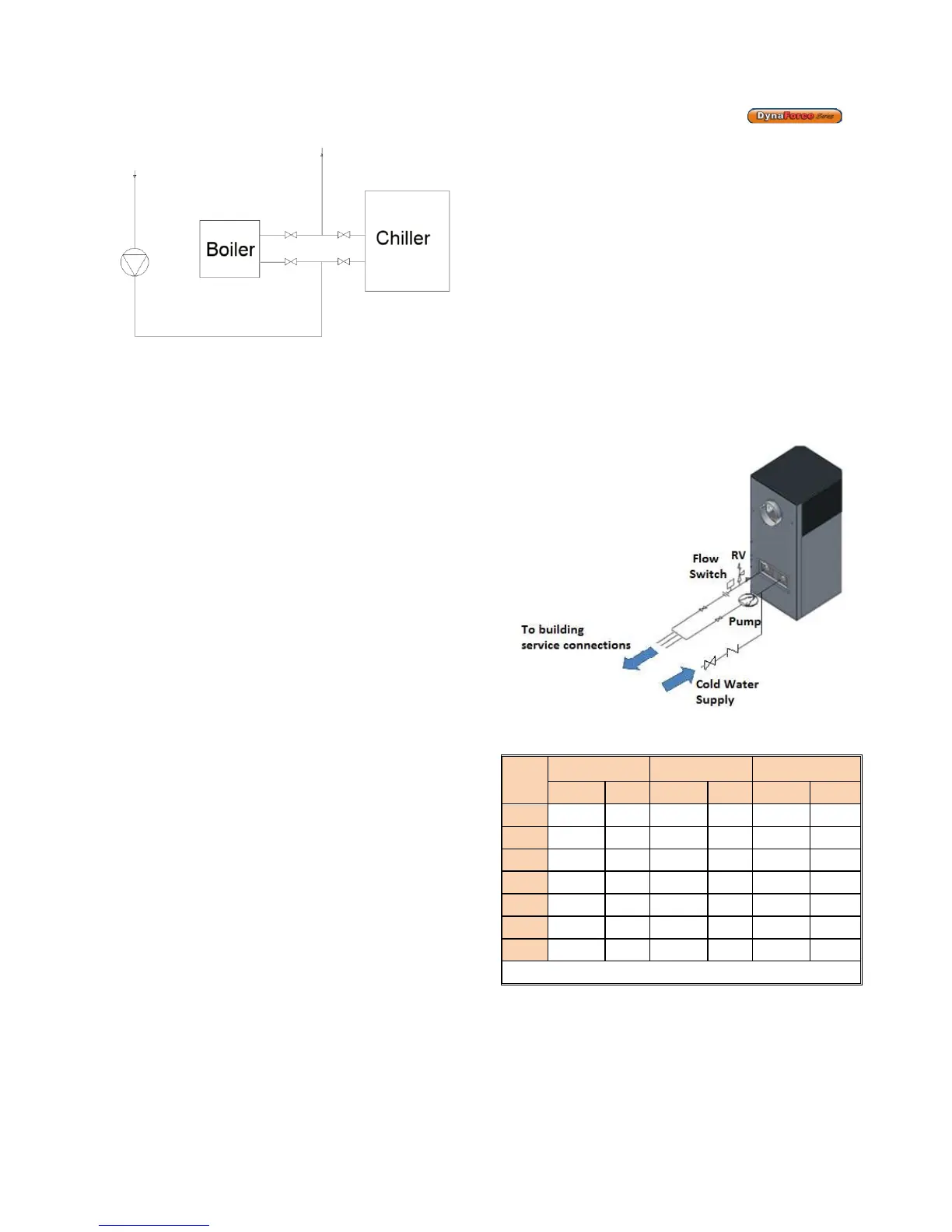
4.7 INSTANTANEOUS WATER HEATER
An instantaneous water heater is designed to deliver hot
water without the use of a storage tank. It is suitable for
applications with variable load such as restaurants,
condominiums, apartments and motels and typically used
in conjunction with tempering valves to achieve
temperature control. In some applications it may be
appropriate to provide a flow through tank to act as a
buffer. Consult factory for recommendations. (See Figure
18)
Figure 18: Typical Instantaneous Water Heating
System
Table 8: Flow and Pressure Drop at a Given
Temperature Rise (DR300-1000)
Model
10
o
F Rise 15
o
F Rise 20
o
F Rise*
US GPM ∆P-Ft. US GPM ∆P-Ft. US GPM ∆P-Ft.
300 57.0 0.5 38.0 0.3 - -
350 66.5 0.7 44.3 0.4 - -
400 76.0 1.0 50.1 0.5 - -
500 95.0 1.6 63.3 0.8 - -
600 113.9 2.5 75.9 1.3 - -
800 152.0 6.6 101.3 3.2 76.0 1.9
1000 189.8 11.4 126.5 5.4 95.0 3.2
* Use for hydronic heating applications only