6.3 LEAD LAG SETUP UP TO 8 BOILERS
The following components are needed for a Lead Lag setup
1) 10k System Sensor
Turn off all the boilers before beginning the setup process.
To setup the Dynaforce® Lead Lag system follow the
instructions:
System Sensor
Insert the supplied 10k system sensor into the building loop.
The wires coming out of the system sensor should be
connected to Sys/Outdr terminals in the junction box.
NOTE
The use of a system sensor is required in lead lag operation.
1) When variable speed main circulators ARE NOT used
the system sensor is to be placed into the return
system piping.
2) When variable speed main circulators are used the
system sensor is to be placed into the supply system
piping.
All SOLA controllers are programmed with a default address of
1. The address of the slave controllers in the system must
have a unique address (1..8).
Sequence of Operation:
When a boiler is set as Lead Lag Master = Enabled and
Modbus address = 1, the controller of this boiler will drive the
lead lag operation.
The outdoor temperature sensor connected to the slave boiler
2 (ie. B-2) will be the outdoor sensor for the lead lag system
• The system temperature sensor connected to boiler 1
(the master) in terminals labeled “Outdr/Sys” in the
junction box will be the control sensor for lead lag
operation.
• The start/stop signal connected to boiler 1 (the
master) at terminals labeled “Remote Operator” will
be the heat demand input for lead lag operation.
When demand for heat is present the lead boiler will start and
uses the lead lag parameters for boiler modulation. After a
period of “Interstage delay” the master boiler compares the
lead lag temperature with the lead lag set point and will check
if:
1) An additional boiler is needed
Lead lag temp < Lead lag setpoint – Add stage Error
threshold
2) Number of boilers remain the same
Lead lag > Lead lag setpoint – Add stage Error
threshold AND
Lead lag temp < Lead lag setpoint + Drop stage Error
threshold
3) A boiler should stop
Lead lag temp > Lead lag setpoint + Drop stage Error
threshold
4) All boilers off
Lead lag temp > Lead lag setpoint + off hysteresis
If the lead lag master system is interrupted the remaining
boilers will operate as standalone boilers based on the Central
Heat or DHW parameters when set to “Enabled”.
Rotation
Rotation time is configurable based on equalized run time
(default) or a fixed rotation schedule.
Interstage Delay
The length of time to wait between starting the next boiler
in sequence. (Default: 2 minutes)
Base Load Rate
When a call for heat is initiated the lead boiler runs up to
the desired base load rate (Default: 80%) and continues to
operate in this fashion based on the above 4 scenarios. If
the lead lag temperature is not satisfied a second boiler is
fired and they would both operate up to 80% fire rate.
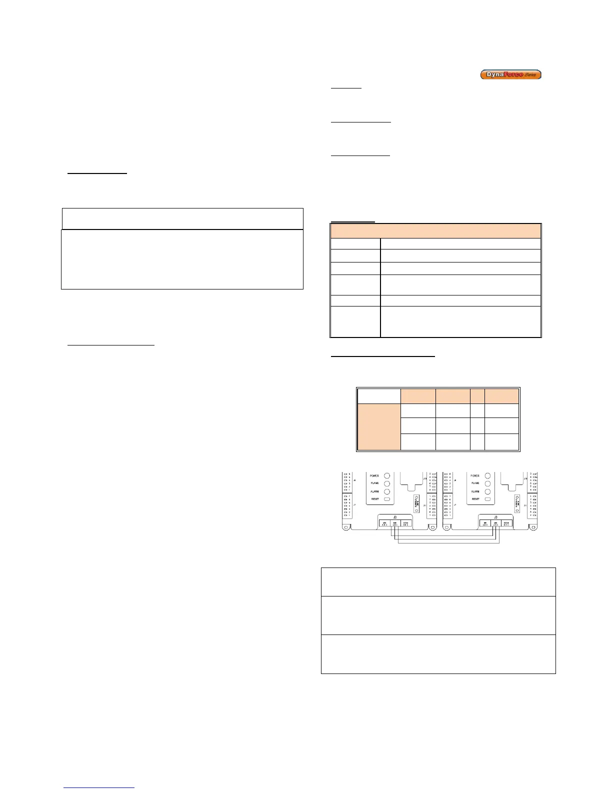
Slave State
Slave Status Manager
Unknown Table entry is unused or empty
Available Slave is operational and ready to use
Add Stage Stage is getting ready to fire
Suspend
Stage
Stage was getting ready but is not needed