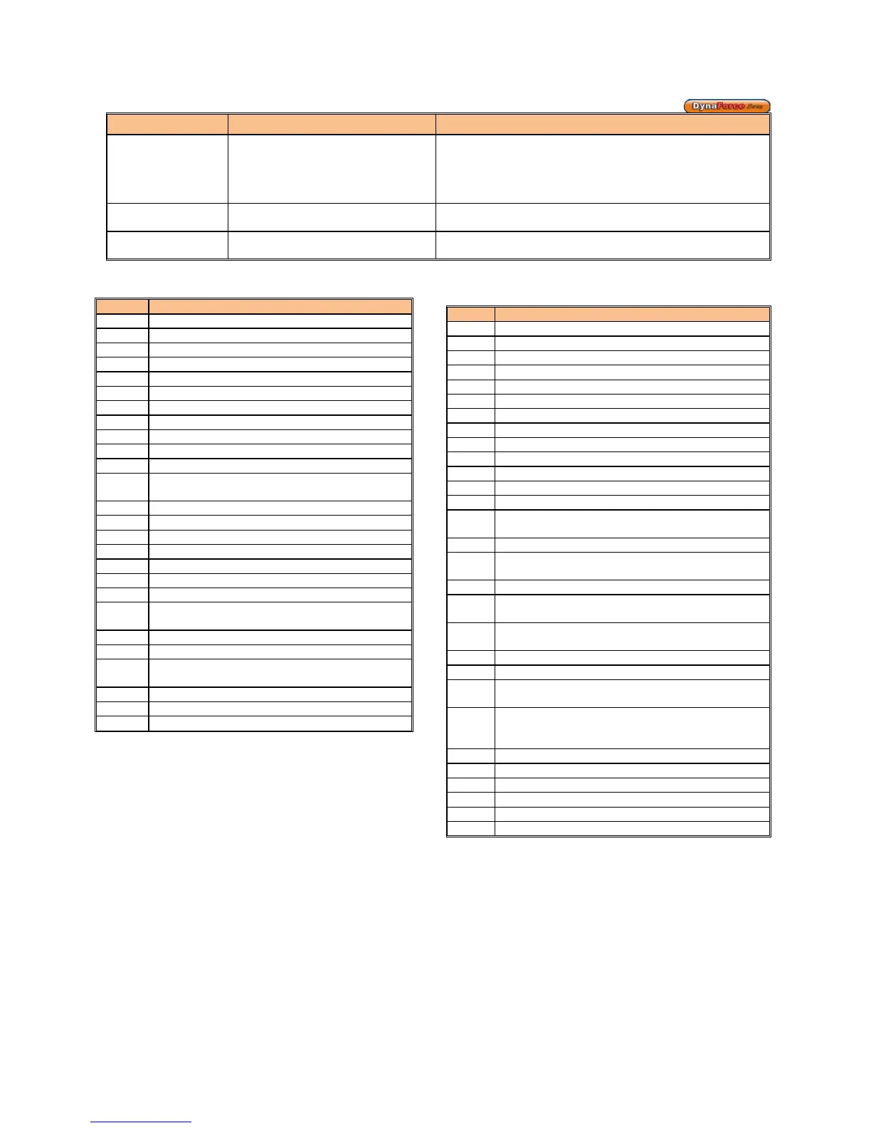
Flame Detection is
out of Sync
• Flame detection is present when no
visible signs of a flame exist
• Lockout: 105, 158
• Verify supply voltage for proper polarity.
• Check external wiring for voltage feedback
• Check internal wiring for proper connections
• Check the flame sensor and verify that it is clean
• Replace Dynaforce® Controller, if necessary
Screen
• Blank display screen • Check wire connections from Dynaforce® Controller to
touchscreen display
Internal Fault
• Lockout: 3-46, 58-60, 97-99, 143-
If fault persists, replace SOLA
2 Waiting for safety data verification
Internal Fault. Replace SOLA Controller
47 Flame rod to ground leakage
49 24VAC low/high
50 Modulation Fault
64 Fan speed not proved, ignition failure
67 Interlock Off, safety circuit is open
79 Heater Outlet high limit tripped
81 Delta T Limit
82
Stack limit tripped (PVC: 149
94 Header sensor fault
95 Stack sensor fault
105 Flame detected out of sequence
106
Flame lost if Main Flame Establishing Period
(MFEP)
108 Flame lost in run
109,
110
Ignition failed
112 Pilot test flame timeout
113 Flame circuit timeout
149 Flame detected
* If an internal hardware error is detected contact Camus®
technical support for troubleshooting procedure.
Table 17: Alert/Hold Codes
29 Burner switch turned OFF
30 Burner switch turned ON
47 Invalid subsystem request occurred
50 Modulation Fault (DR300 – 1000 ONLY)
63 LCI off, safety circuit is open
Setpoint was overridden due to
69 Modulation was overridden due to sensor fault
Modulation rate was limited due to outlet limit
124 Modulation rate was limited due to Delta-T limit
No Lead Lag slaves available to service demand
219
Using backup Lead Lag header sensor due to
sensor failure
Lead lag slave communication timeout.
LCI off, safety circuit is open
283 Demand off during measured purge time
291
Abnormal Recycle: Flame was not on at end of
292
Abnormal Recycle: Flame was lost during Main
Flame Establishing Period
293 Abnormal Recycle: Flame was lost early in Run
Abnormal Recycle: Flame was lost during Run
303-
310
+
Interlock Off, safety circuit is open
324,
374-
379
Hardware flame bias. Flame sensor wire needs to
be re-routed.
550 Delta T inlet/outlet limit was exceeded
+
The alarm LED and alarm contacts are closed and will
remain closed until the ‘RESET’ button is pressed.