26
5.9 ERROR TABLE
The following tables provide a description of all the possible
errors with the Dynaforce® appliance. Errors can be divided into
two groups. Alert errors (will disappear when error is gone) and
lockout errors (can only be reset by the RESET button).
When the control is in error the pump will be running. This is
done to prevent the freezing of the central heating circuit when
the boiler is in error during the winter period. For some non-
volatile lockouts the pump will not be running, see table below
for more details.
Table 12: Lockout codes
Waiting for safety data verification
Internal Fault. Replace SOLA Controller
Flame rod to ground leakage
Fan speed not proved, ignition failure
Interlock Off, safety circuit is open
Heater Outlet high limit tripped
82
Stack limit tripped (PVC: 149
o
F, CPVC: 194
o
F,
250
o
Flame detected out of sequence
106
Flame lost if Main Flame Establishing Period
(MFEP)
* If an internal hardware error is detected contact Camus®
technical support for troubleshooting procedure.
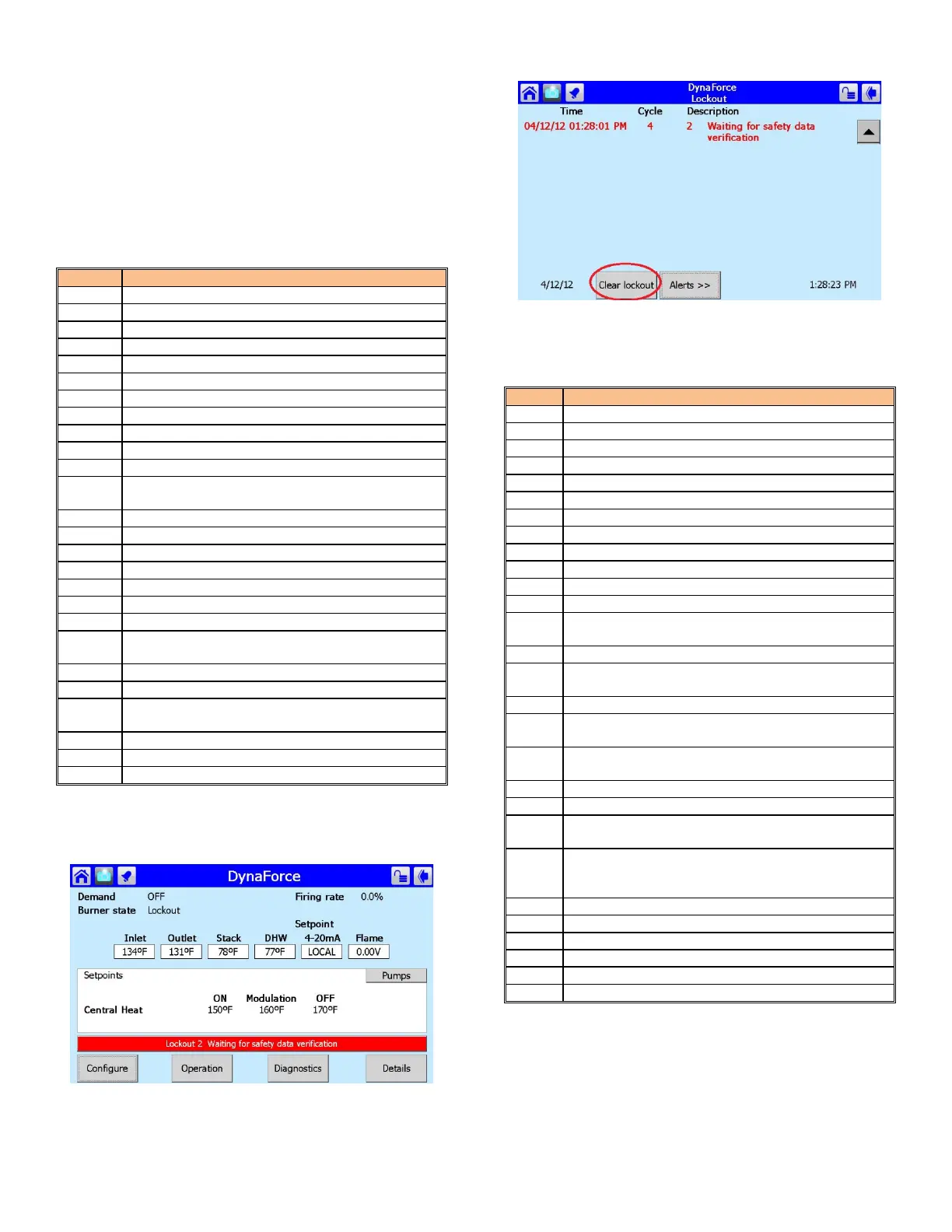
Figure 22: Lockout Condition
To eliminate the lockout error,
1) Press the red bar, indicating a Lockout condition
2) Press the [Lockouts] button
Figure 23: Lockout History
3) Press [Clear Lockout]
Table 13: Alert/Hold Codes
Invalid subsystem reset request occurred
Modulation Fault (DR300 – 1000 ONLY)
LCI off, safety circuit is open
Setpoint was overridden due to sensor fault
Modulation was overridden due to sensor fault
Modulation rate was limited due to outlet limit
Modulation rate was limited due to Delta-T limit
No Lead Lag slaves available to service demand
219
Using backup Lead Lag header sensor due to
sensor failure
Lead lag slave communication timeout.
LCI off, safety circuit is open
Demand off during measured purge time
291
Abnormal Recycle: Flame was not on at end of
Ignition period
292
Abnormal Recycle: Flame was lost during Main
Flame Establishing Period
Abnormal Recycle: Flame was lost early in Run
Abnormal Recycle: Flame was lost during Run
+
Interlock Off, safety circuit is open
374-
Hardware flame bias. Flame sensor wire needs to
be re-routed.
Delta T inlet/outlet limit was exceeded
* If an internal hardware fault is detected contact Camus®
technical support for troubleshooting procedure.
+
The alarm LED and alarm contacts are closed and will remain
closed until the ‘RESET’ button is pressed.