9
NOTE:
Experience has shown that improper installation or
system design, rather than faulty equipment, is the cause
of most operating problems
1.8 BOILER ROOM OPERATING CONDITION
• Due to low jacket losses from the appliance, temperatures
in a typical boiler room may drop significantly; supplemental
heat is required to maintain ambient temperature at
acceptable levels.
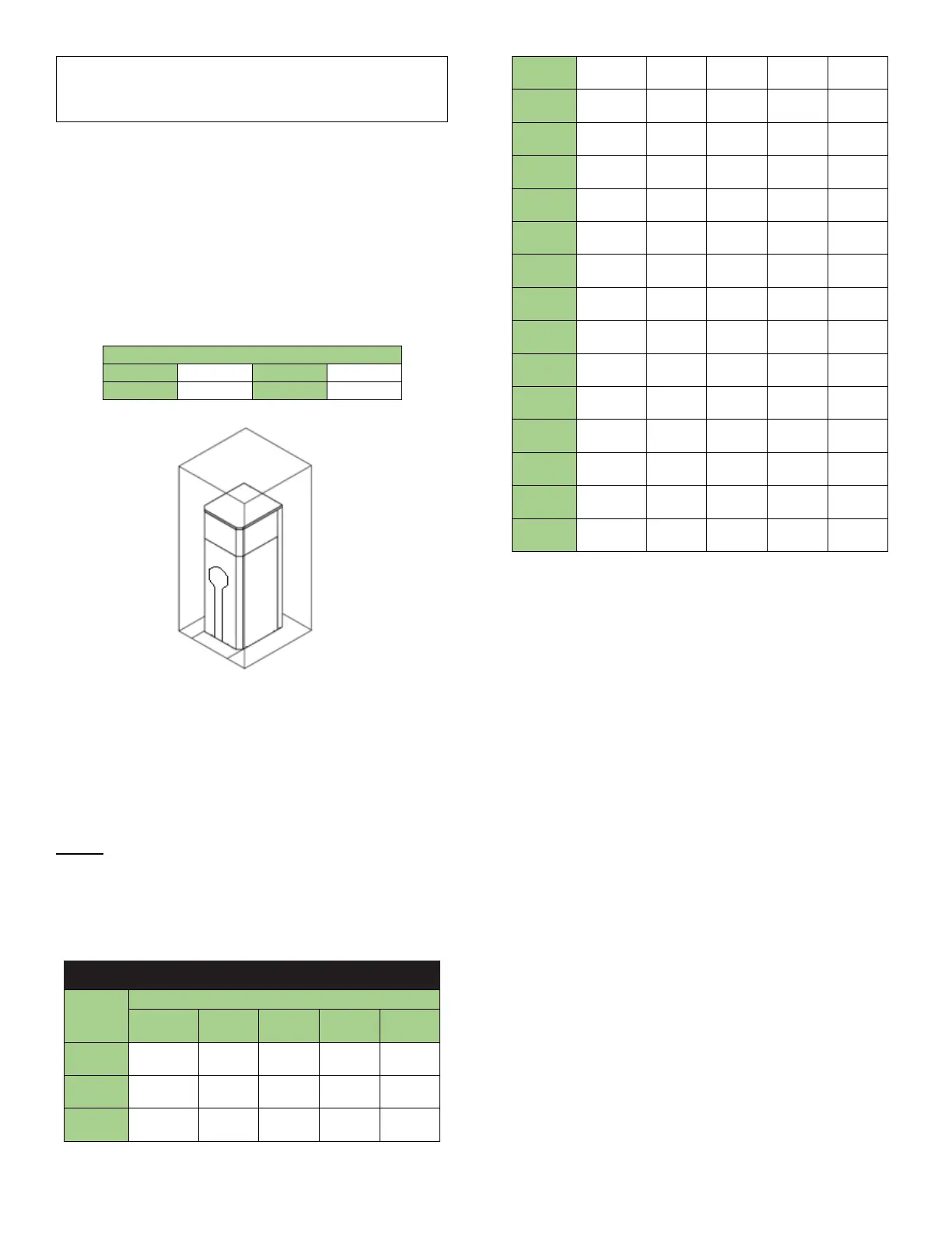
1.9 CLEARANCE FROM COMBUSTIBLE
MATERIAL
This appliance is suitable for alcove (a closet without a door)
installation with minimum clearances to combustibles as follows:
Table 1: Clearances from combustibles
Clearances from Combustibles
Figure 4: Clearance from Combustibles
When placing the appliance be aware that a minimum clearance
of 24” (60cm) must be provided at the front to allow easy access
to the heat exchanger.
When installed directly on combustible flooring, the appliance
shall be installed on a metal panel extending beyond the full
width and depth of the appliance by at least 3 inches (76.2mm)
in any direction. The floor must be strong enough to support the
full weight of the heater.
NOTE: Clearances from combustible construction are noted on
the appliance rating plate
Maintain minimum specified clearances for adequate operation.
All installations must allow sufficient space for servicing the vent
connections, water pipe connections, circulating pump, bypass
piping and other auxiliary equipment, as well as the appliance
Table 2: Service Clearances
Service Clearances
Model
Service Clearance, Inches (cm)
Top
Back Front
300
*
350
*
400
*
500
*
600
*
800
*
1000
*
1200
*
1400
*
1600
1800
2000
2500
3000
3500
4000
4500
5000
*Allow adequate space for the venting in addition to 6”
clearance to combustibles.
1.10 INSTALLATION PROCEDURE AND
LOCATION OF UNIT
Install this appliance in a clean, dry location with adequate air
supply.
• Do not locate this appliance in an area where it will be
subject to freezing unless precautions are taken.
Radiant losses from the Dynaforce® are minimal and
should not be relied on to keep the appliance room
warm.
• The appliance should be located close to a floor drain
in an area where leakage from the appliance or
connections will not result in damage to the adjacent
area or to lower floors in the structure, it is
recommended that a suitable drain pan, adequately
drained, be installed under the unit. Under no
circumstances is the manufacturer to be held
responsible for water damage in connection with this
unit, or any of its components.
• If the appliance is installed above the level of the
building’s radiation system, a low water cut-off device
must be installed above the heat exchanger inlet/outlet
connections. Some local codes require the installation
of a low water cut-off on all systems
• When placing the appliance be aware that a minimum
clearance of 24” must be provided at the front to allow
easy access to the heat exchanger.