45
6.2.3 Statistics Configuration
Menu
Group
Selection
Menu
Group
Parameter Selection Description
Boiler
pump
cycles
number of cycles
the boiler pump
Burner
cycles
number of cycles
the burner has
Displays burner
run time in hours
CH pump
cycles
number of cycles
the CH pump has
DHW pump
cycles
number of cycles
the DHW pump
System
pump
cycles
number of cycles
the system pump
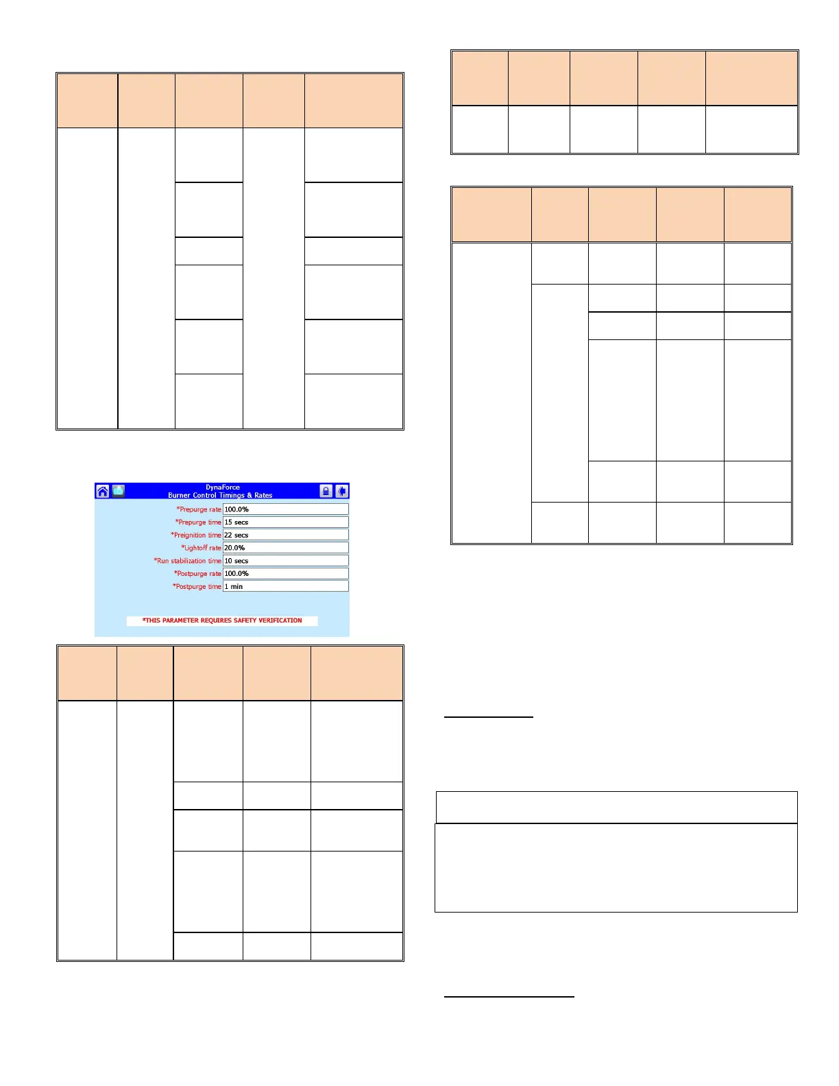
6.2.4 Burner Control Timing and Rates
Figure 27: Burner Control Timing and Rates
Menu
Group
Selection
Menu
Group
Parameter Selection Description
Burner Control Timing and Rates
Prepurge
rate
3000 RPM
speed (Default:
DR300 – 1000:
3000 RPM,
DR1200 – 5000:
Prepurge time
(Default: 25 sec)
Stabilization
10 sec
establishing
Postpurge
rate
3000 RPM
speed (Default:
DR300 – 1000:
3000 RPM,
DR1200 – 5000:
Postpurge time
(Default 25 sec)
6.2.5 Burner Control Ignition
Menu
Group
Selection
Menu
Group
Parameter Selection Description
Lightoff
rate
3000 RPM
DR1200 –
speed
6.2.6 Sensor Configuration
Menu Group
Selection
Menu
Group
Parameter Selection Description
Sensor
Configurations
S1 (J8-4)
sensor
single non-
Inlet Sensor
4-20mA
S5 (J8-11)
sensor
10K NTC
single non-
safety
Sensor:
Standalone
boiler or
Slave boiler
Header
sensor:
Master
S6S7 (J9-
1,3) sensor
single non-
Sensor
S8S9 (J9-
4,6) sensor
single non-
Stack
Sensor
6.3 LEAD LAG SETUP UP TO 8 BOILERS
The following components are needed for a Lead Lag setup
1) 10kΩ System Sensor
Turn off all the boilers before beginning the setup process.
To setup the Dynaforce® Lead Lag system follow the
instructions:
System Sensor
Insert the supplied 10kΩ system sensor into the building loop.
The wires coming out of the system sensor should be connected
to Sys/Outdr terminals in the junction box.
NOTE
The use of a system sensor is required in lead lag operation.
1) When variable speed main circulators ARE NOT used
the system sensor is to be placed into the return
system piping.
2) When variable speed main circulators are used the
system sensor is to be placed into the supply system
piping.
All SOLA controllers are programmed with a default address of
1. The address of the slave controllers in the system must
have a unique address (1..8).
Sequence of Operation: